Directly-down backlight module unit

A backlight module and direct-type technology, which is applied in the field of direct-type backlight modules, can solve problems affecting color purity, LED frequency drift, and shorten working life, and achieve the effects of suppressing spectrum drift, expanding heat dissipation area, and improving working life

Inactive Publication Date: 2008-09-03
上海广电光电子有限公司
View PDF0 Cites 40 Cited by
  • Summary
  • Abstract
  • Description
  • Claims
  • Application Information

AI Technical Summary

Problems solved by technology

[0003] The LED light source used in the current direct-type backlight module is to arrange a plurality of LED particles on the backplane according to certain requirements to form an LED light source array. The emitted light is "mixed", and the larger the spacing between the LED particles, the greater the "mixing" distance required, so the size of the spacing between the LED particles and the height of the light-emitting surface of the backlight module (that is, the backlight The thickness of the module) has a lot to do with it, but for cost considerations, the arrangement spacing between LEDs should not be too small (that is, the number of LED particles should not be too much), so that there is no way to make the direct LED light source The backlight module reaches the ideal thickness, making it difficult to achieve thin design
Moreover, when the LED light source array is working, due to the low efficiency of converting electrical energy into light energy, a large amount of heat energy will be generated. If the heat dissipation cannot be effectively carried out, the frequency drift of the LED will occur, and the spectral width will increase accordingly, which will affect the color purity.
At the same time, LED overheating will reduce its luminous intensity and shorten its working life.

Method used


Image

  • Directly-down backlight module unit
  • Directly-down backlight module unit
  • Directly-down backlight module unit

Examples


Embodiment Construction

[0019] Embodiments of the present invention will be further described below in conjunction with accompanying drawings:

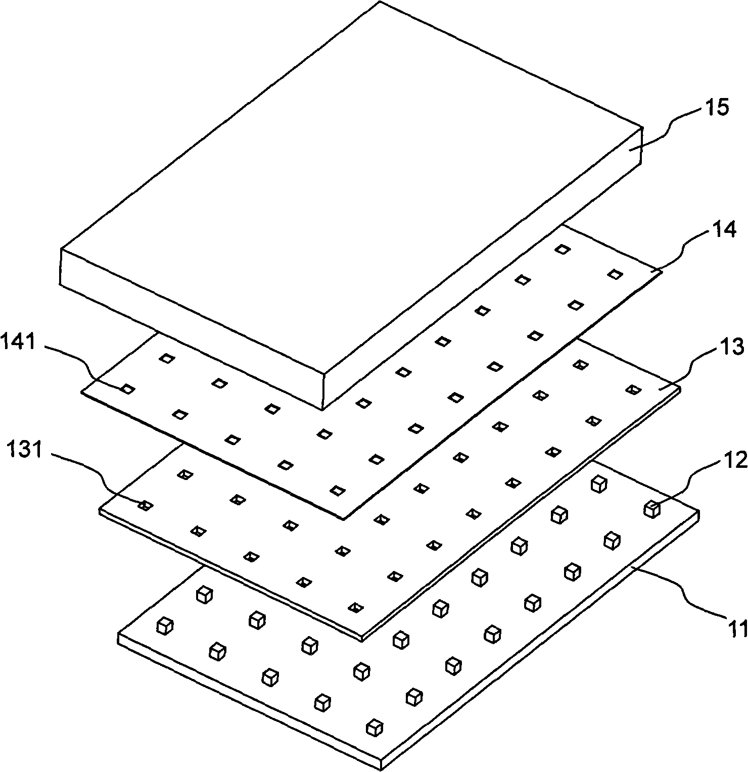
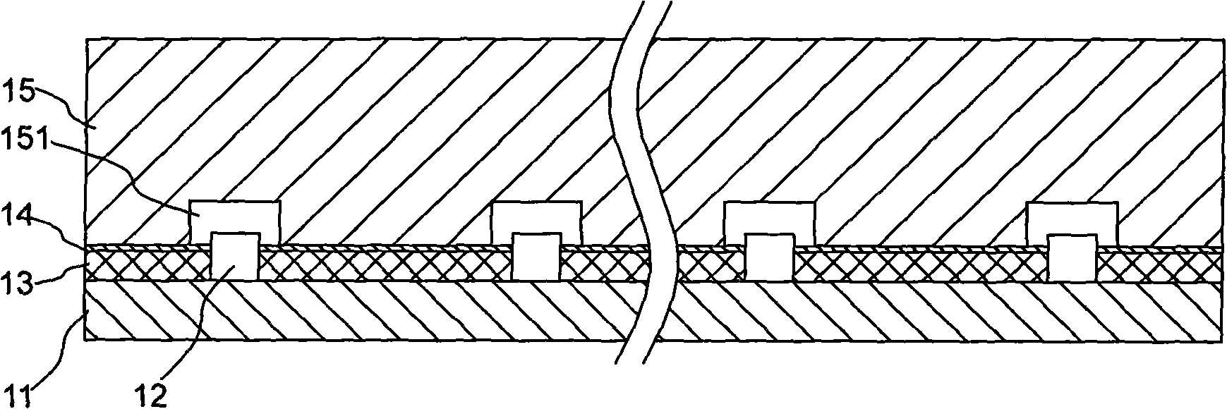
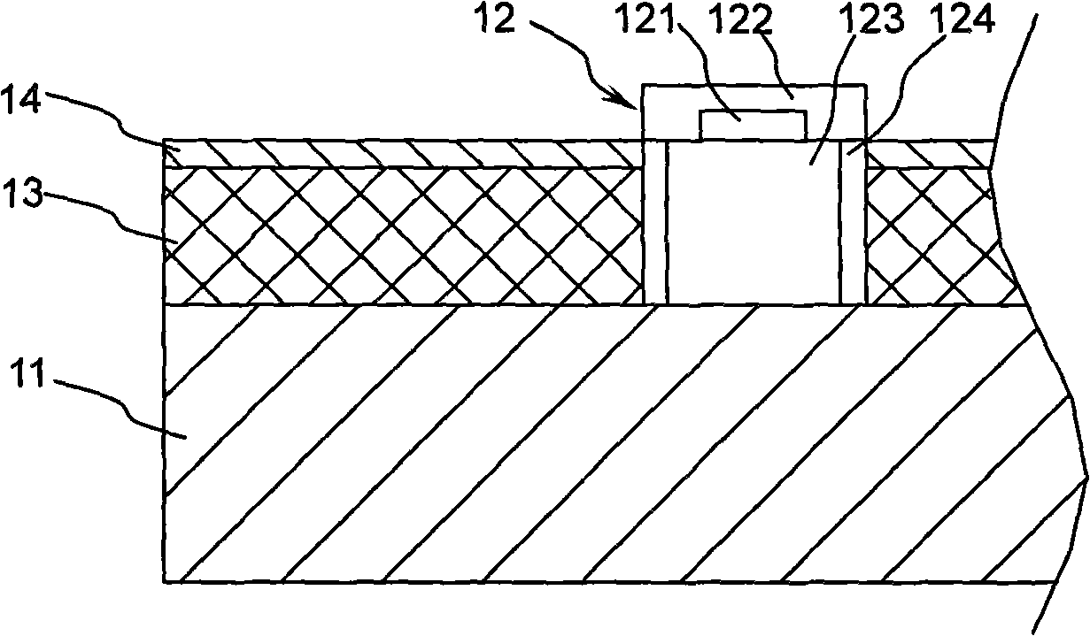
[0020] figure 1 It is an exploded schematic view of the direct type backlight module according to the embodiment of the present invention; figure 2 yes figure 1 A cross-sectional view of a direct-lit backlight module. As shown in the figure, the direct-type backlight module of the present invention includes a backplane 11; several LED light sources 12 are pasted on the backplane 11 by adhesive or solder according to certain arrangement requirements; a printed circuit board (PCB) 13. Place it on the back plate 11, and electrically connect the LED light source 12. There is an opening 131 hollowed out at the corresponding position of the LED light source 12, so that the LED light source 12 can pass through; the reflector 14 is placed on the printed circuit board 13 On the top, there is an opening 141 hollowed out at the corresponding position of the LED lig...


PUM


Abstract

The invention discloses a direct illumination-type backlight module using the LED light source. The direct illumination-type backlight module comprises a backplate; a plurality of LED light sources adhesive to the backplate; a printed circuit board above the backplate and electrically connected with the LED light source and provided with an opening for the LED light source at the corresponding position of the LED light source; a reflection piece above the printed circuit board and provided with an opening for the LED light source at the corresponding position of the LED light source; a guide light device comprising a bottom and a light extraction face on the reflection piece and provided with a column groove at the corresponding position of the LED light source at the bottom, wherein the groove bottom of the column groove is of conoid and is coated with the reflection material. The direct illumination-type backlight module is favourable to the ultra thinning processe of the liquid crystal display device with good heat emission effect.

Description

technical field [0001] The invention relates to a backlight module of a liquid crystal display, in particular to a direct-down backlight module using an LED light source. Background technique [0002] At present, liquid crystal display has become the mainstream in the field of flat panel display. The backlight module is one of the key components of the liquid crystal display. Since the liquid crystal display itself does not emit light, the function of the backlight module is to provide a light source with sufficient brightness and uniform distribution, so that it can display images normally. Compared with other backlight sources, the most significant advantage of LED light source is that it can provide unprecedented color reproduction. By selecting LEDs with appropriate wavelengths and matching color filters, the color reproduction range of LED backlight sources can reach 105% or even 120% of NTSC (National Television System Committee) standards. In comparison, traditional...

Claims


Application Information

Patent Timeline
Patent Type & Authority Applications(China)
IPC IPC(8): G02F1/13357F21V23/06F21V8/00G02B6/00F21Y101/02G02F1/1335
Inventor 蔡文彬
Owner 上海广电光电子有限公司
Why Eureka
Try Eureka