Self-tightening type packing box seal displacement buffer, and loop reactor

A technology of stuffing box and buffer, which is applied in the direction of engine sealing, chemical instruments and methods, engine components, etc. It can solve the problems of reduced sealing performance, slightly poor sealing performance, and the dynamic sealing function of packing can not be well exerted, etc. , to achieve the effect of high sealing reliability and good self-tightening

Active Publication Date: 2012-12-26
THE CHALLENGE PETROCHEM MACHINERY CORP
View PDF7 Cites 1 Cited by
  • Summary
  • Abstract
  • Description
  • Claims
  • Application Information

AI Technical Summary

Problems solved by technology

"In the above technical scheme, since the displacement buffer with stuffing box double-seal structure only has the double-seal structure of the dynamic seal of the packing and the seal of the rubber sealing ring, its sealing performance is slightly poor, and the dynamic sealing function of the packing Can not play well, reducing its sealing performance

Method used


Image

  • Self-tightening type packing box seal displacement buffer, and loop reactor
  • Self-tightening type packing box seal displacement buffer, and loop reactor

Examples


Embodiment 1

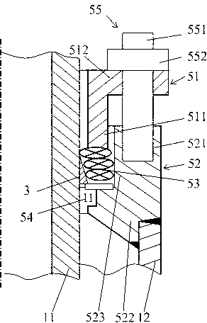
[0041] A specific embodiment of a self-tightening stuffing box seal displacement buffer of the present invention, as figure 2 As shown, it includes a packing compression ring 51, a sealing letter 52, a packing 53, a rubber sealing ring 54 and a fastener 55. The packing compression ring 51 and the sealing box 52 cooperate with each other. One section compresses the gap between the inner side 523 of the sealing box 52 and the outer wall surface of the inner pipe 11 by compressing the packing 53, and the other section of the packing pressure ring 51 is connected to the seal by the fastener 55. The sealing box 52 is connected with the outer tube 12, and the rubber sealing ring 54 is arranged in the gap between the inner side 523 of the sealing box 52 and the outer wall surface of the inner tube 11, and is located in the packing 53 , which also includes an inclined sealing body 3 , the inclined sealing body 3 is connected to the outer wall surface of the inner pipe 11 , and the ou...

Embodiment 2

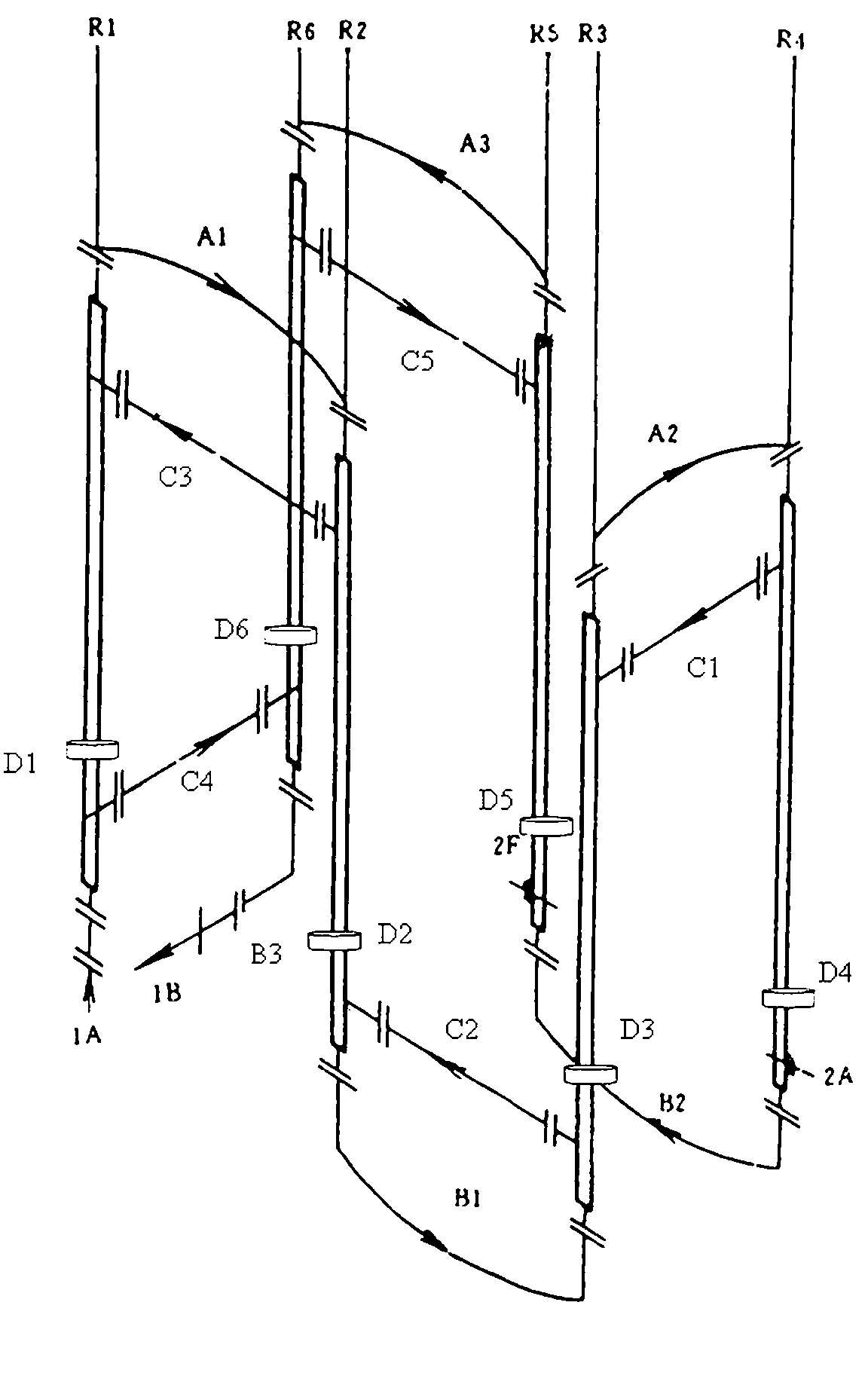
[0052] A specific embodiment of a loop reactor of the present invention includes a straight casing, a jacket connecting pipe, an elbow and a mounting support, the straight casing includes an inner pipe 11 and an outer pipe 12, and the elbow The head and the inner pipe 11 are sequentially connected in series to form a communication channel for conveying and reacting the reaction material. The jacket flow channel formed between the outer tubes 12 is connected in series to form a communication channel for conveying cooling medium, and the mounting support is arranged at the lower part of the outer tube 12 so that the straight sleeve is divided into the upper pipe section of the straight sleeve and the straight sleeve. The lower pipe section of the casing, the straight casing is provided with a displacement buffer between the inner pipe 11 and the outer pipe 12 for absorbing the thermal expansion and contraction displacement between the inner pipe 11 and the outer pipe 12 The disp...


PUM


Abstract

The invention discloses a self-tightening type packing box seal displacement buffer and a loop reactor provided with the self-tightening type packing box seal displacement buffer, wherein the self-tightening type packing box seal displacement buffer further comprises an inclined sealing body based on the prior art; the inclined sealing body is connected with the outer wall surface of an inner pipe, and the outer side surface of the inclined sealing body is closely placed against the packing. The self-tightening type packing box seal displacement buffer used in the loop reactor is the above self-tightening type packing box seal displacement buffer. The self-tightening type packing box seal displacement buffer provided by the invention not only has the property of absorbing moving of expanding and shrinking but also has three sealing functions comprising a primary seal of a rubber seal ring, a dynamic seal of the packing and a self-tightening type seal of the inclined seal body after the packing is extruded, the dynamic sealing is enhanced, therefore, compared with the packing box type double-seal-structure displacement buffer in the prior art, the self-tightening type packing box seal displacement buffer has advantages of higher sealing reliability and better self-tightening property due to the added seal enhancement.

Description

technical field [0001] The invention relates to the petrochemical special equipment technology in mechanical equipment engineering, in particular to a self-tightening stuffing box sealing displacement buffer and a loop reactor with the self-tightening stuffing box sealing displacement buffer. Background technique [0002] The loop reactor is mainly used in the production equipment of polypropylene and polyethylene in the petrochemical field, and is also commonly used in the production equipment such as mud coolers and butene coolers in the petrochemical field. [0003] In the prior art, a common loop reactor includes a number of straight casing pipes, corresponding jacketed connecting pipes, elbows and connecting beams, which are set according to the size of the production capacity, wherein every two straight casing pipes The inner pipe and the two elbows are sequentially connected in series to form a communicating channel. Because the polymerization reaction is an exotherm...

Claims


Application Information

Patent Timeline
IPC IPC(8): B01J19/00F16J15/00
Inventor 陈孙艺
Owner THE CHALLENGE PETROCHEM MACHINERY CORP
Why Eureka
Try Eureka