Eureka AIR delivers breakthrough ideas for toughest innovation challenges, trusted by R&D personnel around the world.

Cleaning device

A technology for cleaning and cleaning mechanisms, applied in the direction of heating devices, solar thermal devices, cleaning methods and appliances, etc., can solve the problems of reducing the size or height of the brush holding device, and the inconspicuous height, so as to achieve safe operation and high The effect of operational safety

Inactive Publication Date: 2012-12-26
安东·耶格
View PDF6 Cites 8 Cited by
  • Summary
  • Abstract
  • Description
  • Claims
  • Application Information

AI Technical Summary

Problems solved by technology

[0003] The disadvantage is that, in devices of the type of construction described above, the diameter of the cylindrical brushes can be relatively large, especially when only relatively small, inconspicuous height
In most cases, reducing the diameter may not help here, because the size or height of the brush holder cannot be correspondingly reduced arbitrarily, and in addition, cylindrical brushes that are too thin may cause other problems. shortcoming

Method used


Image

  • Cleaning device
  • Cleaning device
  • Cleaning device

Examples


Embodiment Construction

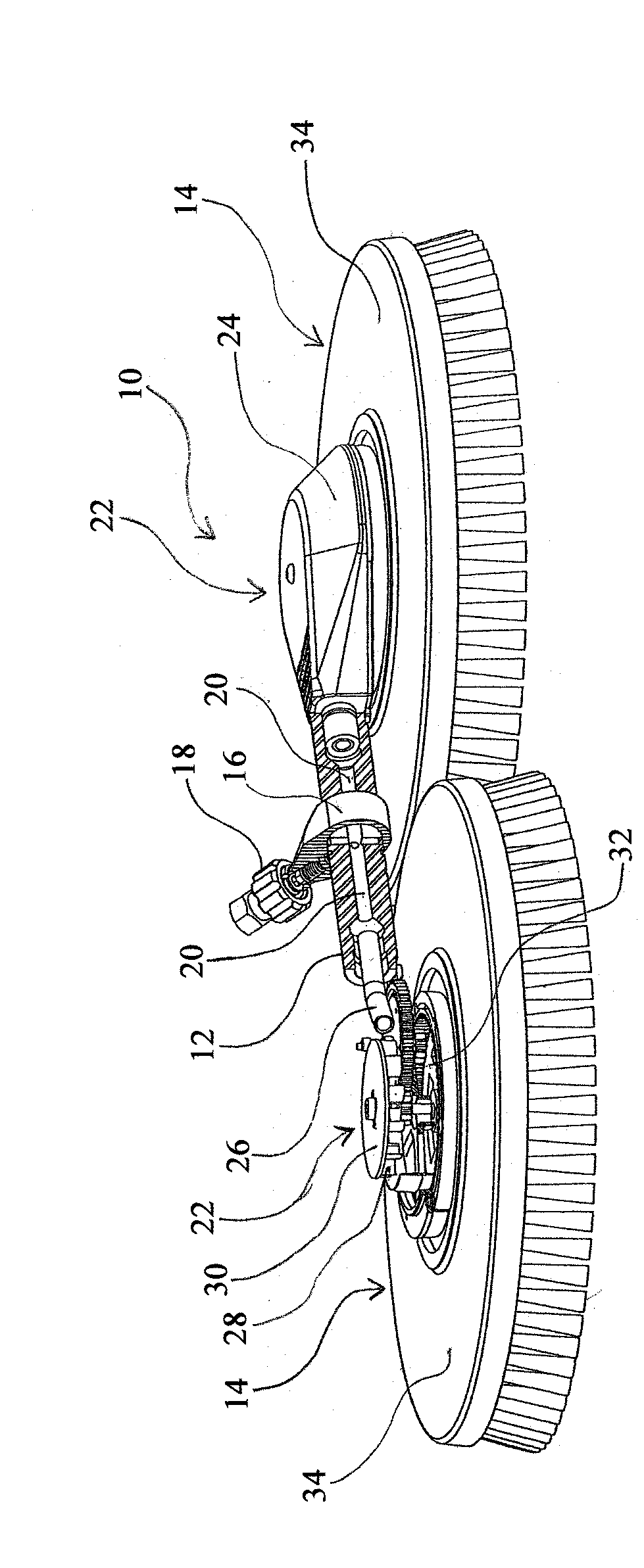
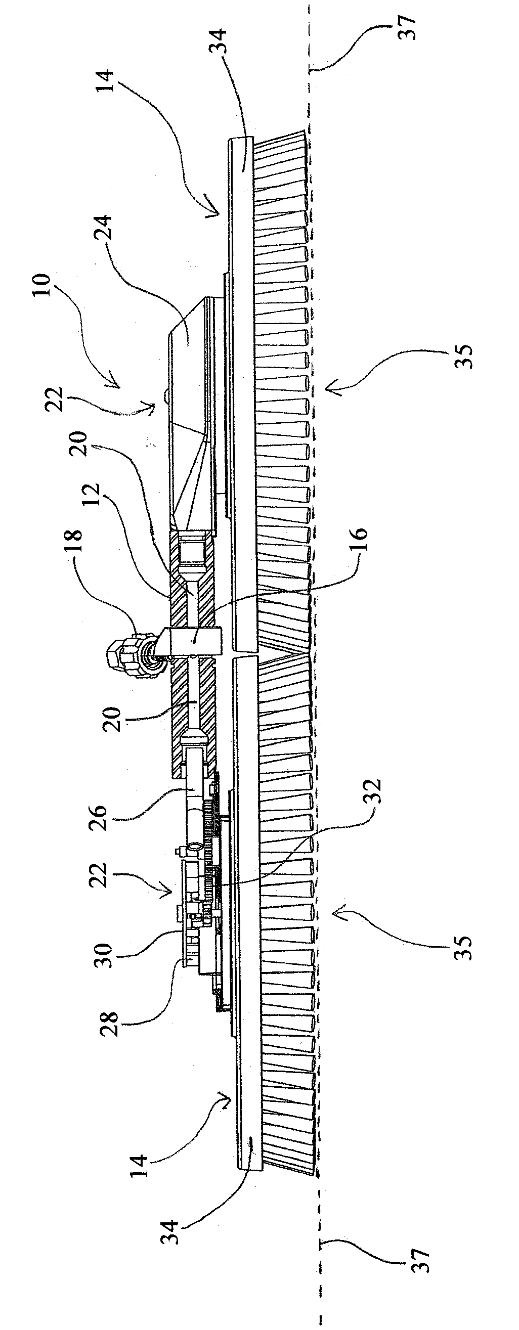
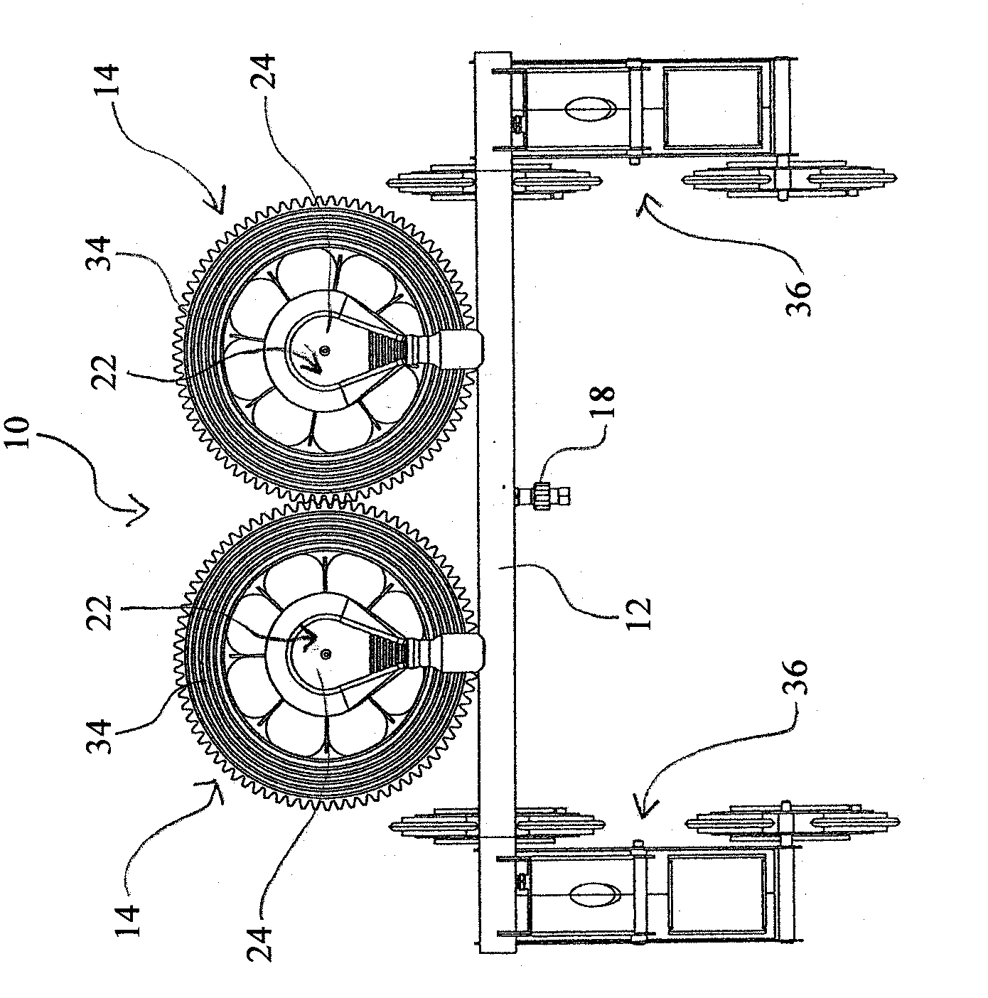
[0025] Such as Figure 1A and 1B As shown in , the device 10 according to the first embodiment of the present invention comprises an elongated frame 12 and two cleaning mechanisms 14 axially arranged on opposite ends of the frame 12 .

[0026] The support 12 has a hinge 16 centrally between the two cleaning elements 14 , into which a connecting element 18 is inserted which is designed for the connection of an external liquid supply line, in particular a hose or a nozzle. The inclination of the external liquid supply line can be adjusted relative to the working plane with the aid of the hinge 16 . The support 12 is provided with a channel extending in the axial direction on both sides of the connecting means 18 and serves as a liquid supply line 20 from the connecting means 18 to the two cleaning means 14 .

[0027] The cleaning means 14 is connected axially on the end side to a liquid supply line 20 . For this purpose, an axial outlet 26 is provided at both ends of the liqui...


PUM


Abstract

The invention relates to a device for cleaning surfaces, especially surfaces of a solar energy device on a roof. The device comprises a bracket and at least two cleaning mechanisms connected with the bracket, wherein the cleaning mechanisms respectively comprise brushes and liquid driving devices for the brushes, the brushes are made to rotate along the axle extending from the working surfaces of the brushes by using the liquid driving devices, the cleaning mechanisms are arranged on the bracket in a way that a common working surface is at least basically defined on the working surfaces of the brushes.

Description

technical field [0001] The invention relates to a device for cleaning surfaces, in particular for cleaning the surfaces of solar installations on roofs. Background technique [0002] Such a device is known in principle from the prior art and comprises a cylindrical brush with bristles directed radially outwards with respect to its longitudinal axis, wherein the brush can be encircled by a longitudinal axis extending parallel to the surface to be cleaned. The axis turns into a rotary motion. [0003] The disadvantage is that, in devices of the type of construction described above, the diameter of the cylindrical brushes can be relatively large, especially when the conforming configuration above the surface to be cleaned in any case has only relatively small, When the height is not obvious. In most cases, reducing the diameter may not help here, because the size or height of the brush holder cannot be correspondingly reduced arbitrarily, and in addition, cylindrical brushes ...

Claims


Application Information

Patent Timeline
Patent Type & Authority Applications(China)
IPC IPC(8): B08B1/04
CPCY02B10/20B08B1/04B08B1/002Y02E10/40B08B3/04F24J2/461F24S40/20B08B1/12B08B1/32
Inventor 安东·耶格
Owner 安东·耶格
Why Eureka
Eureka Blog
Learn More