
Adjustable cleaning clamp

A cleaning fixture and to-be-cleaned technology, applied in the field of lens cleaning, can solve the problems of high cost, unfavorable cleaning, and large contact area between the lens and the groove, etc.

Inactive Publication Date: 2012-12-26
HUBEI W OLF PHOTOELECTRIC TECH CO LTD
View PDF7 Cites 0 Cited by
  • Summary
  • Abstract
  • Description
  • Claims
  • Application Information

AI Technical Summary

Problems solved by technology

[0003] The current lens cleaning fixture is two flat plates with grooves fixed together by screws, and the lenses are placed flat in the grooves. The problem is that the lenses are placed flat, and the grooves can only hold lenses slightly smaller than their specifications. The application of the fixture Limited, different lenses require specially manufactured fixtures of different specifications, which is troublesome and costly; in addition, the contact area between the lens and the groove is large when placed flat, which is not conducive to cleaning

Method used


Image

  • Adjustable cleaning clamp

Examples


Embodiment

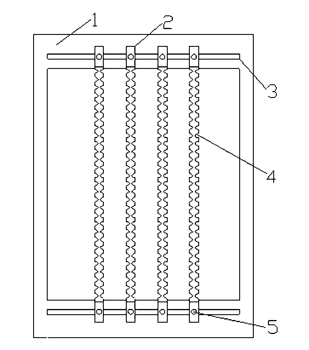
[0013] As shown in the drawings, the adjustable cleaning fixture includes a bottom frame 1 and four clamping bars 2 arranged in parallel. There are through grooves 3 on two opposite sides of the bottom frame 1, and the through grooves 3 are pierced There are screws 5 to fix the two ends of the clip bar 2 on the bottom frame 1, and each clip bar 2 has a plurality of vertical grooves 4 on the two side walls, and the groove diameter of the lower part of the vertical groove 4 is smaller than that of the upper part, which is used for connecting with the bottom frame 1. The vertical grooves of the adjacent clip bars jointly support the lens to be cleaned.

[0014] When in use, according to the specifications of the lens to be cleaned, move the position of the clamp bar 2 along the through groove 3, adjust the size of the enclosed space of the vertical slot 4 of two adjacent clamp bars, then put the lens vertically, and finally place the clamp flat It can be cleaned after entering th...


PUM


Abstract

The invention relates to an adjustable cleaning clamp comprising a bottom frame and at least two parallel battens; through troughs are arranged on two opposite sides of the bottom frame; screws penetrate through the troughs to fix both ends of the battens onto the bottom frame; each batten is provided with a plurality of vertical grooves on two side walls; and the groove diameter at the lower part of each vertical groove is less than that at the upper part of each vertical groove, and each vertical groove is used for supporting a lens to be cleaned together with the vertical groove of the adjacent batten. According to the adjustable cleaning clamp, the vertical grooves of the two battens are used for enclosing and clamping the lens to be cleaned, the size of a space enclosed by the vertical grooves can be adjusted only by adjusting the spacing between the battens, so that the adjustable cleaning clamp is applicable to lenses with various specifications.

Description

technical field [0001] The invention relates to the field of lens cleaning, in particular to an adjustable cleaning jig. Background technique [0002] In the preparation process of optical lenses used in digital cameras, CCD cameras and other equipment, the raw materials need to be cut into middle pieces, glued and then cut in batches, rounded into lens cylinders, and then the lenses are separated into individual pieces through the glue removal process. However, there are still hard-to-wipe stains caused by glue, glue remover, etc. on the surface of the small disc, which must be cleaned thoroughly. [0003] The current lens cleaning fixture is two flat plates with grooves fixed together by screws, and the lenses are placed flat in the grooves. The problem is that the lenses are placed flat, and the grooves can only hold lenses slightly smaller than their specifications. The application of the fixture Limited, different lenses require specially manufactured fixtures of diffe...

Claims


Application Information

Patent Timeline
IPC IPC(8): B08B13/00
Inventor 奂微微
Owner HUBEI W OLF PHOTOELECTRIC TECH CO LTD
Features
  • Generate Ideas
  • Intellectual Property
  • Life Sciences
  • Materials
  • Tech Scout
  • Unparalleled Data Quality
  • Higher Quality Content
  • 60% Fewer Hallucinations
Learn More