Retractor for safety belt and safety belt assembly

A retractor and seat belt technology, applied in the field of seat belts, achieves the effects of simple and controllable stress conditions, improved accuracy, and improved stability

Active Publication Date: 2012-12-26
和励科技有限公司
View PDF8 Cites 13 Cited by
  • Summary
  • Abstract
  • Description
  • Claims
  • Application Information

AI Technical Summary

Problems solved by technology

[0011] The present invention provides a retractor for a safety belt ...

Method used


Image

  • Retractor for safety belt and safety belt assembly
  • Retractor for safety belt and safety belt assembly
  • Retractor for safety belt and safety belt assembly

Examples


no. 1 example

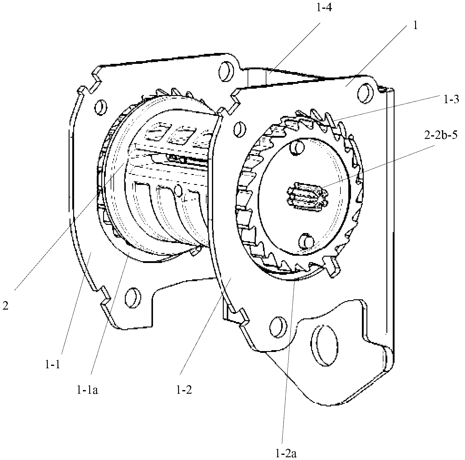
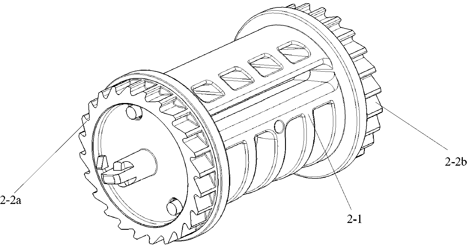
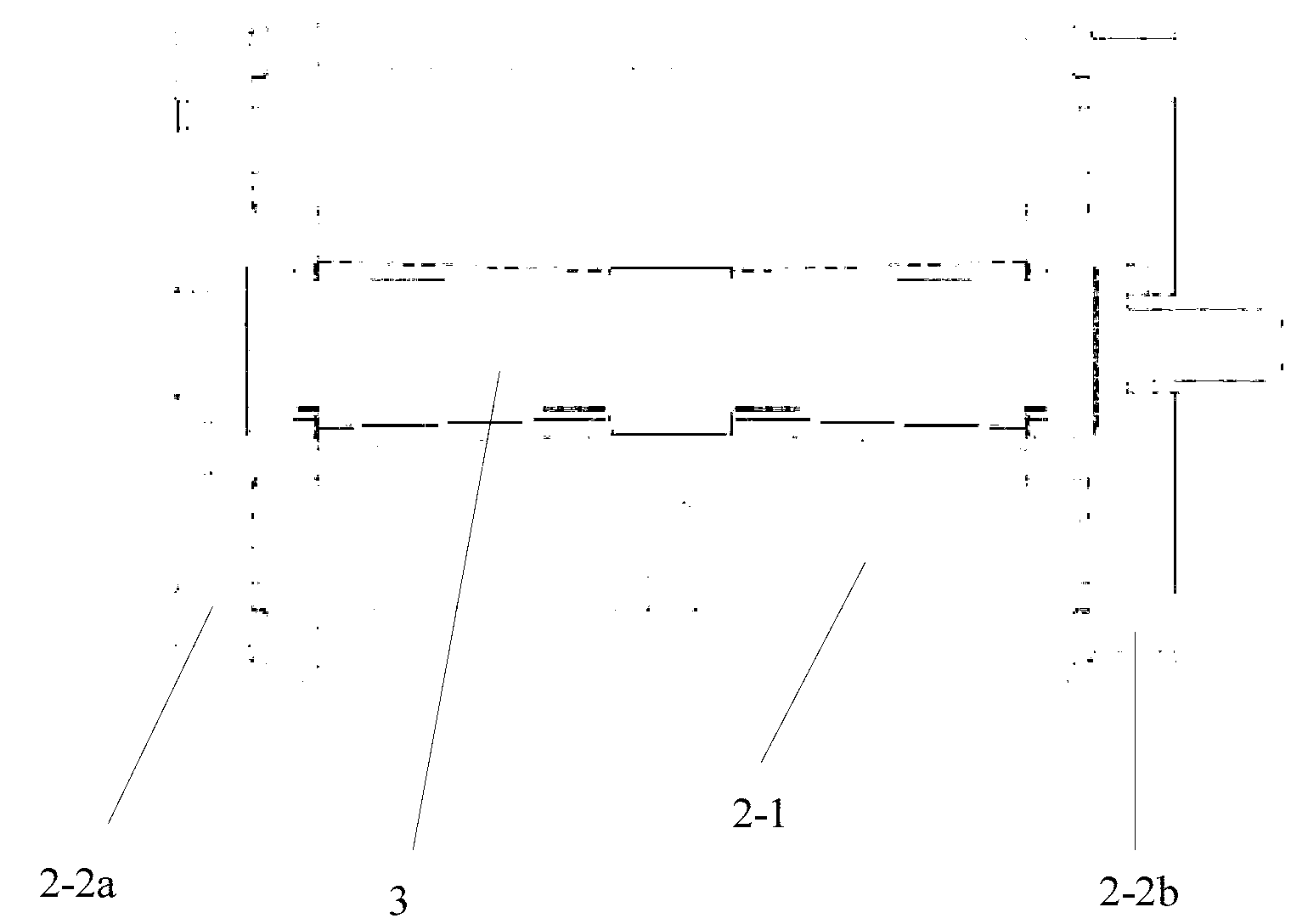
[0051] figure 1 It is a structural schematic diagram of the first embodiment of the retractor for safety belts of the present invention, figure 2 for figure 1 Schematic diagram of the scroll structure in ; image 3 for figure 2 A cross-sectional view along the axis of the reel; Figure 4 An exploded view of the assembly for the reel and torsion bar.

[0052] Please see figure 1 , in this embodiment, the retractor includes a retractor frame 1, a reel 2 and a torsion bar 3 ( Figure 4 shown in

[0053] Wherein, the retractor frame 1 is U-shaped, which includes two opposite side walls: a first side wall 1-1 and a second side wall 1-2. It also includes two third walls 1-4 connecting the first side wall 1-1 and the second side wall 1-2. Corresponding positions on the first side wall 1-1 and the second side wall 1-2 are respectively provided with a circular first through hole 1-1a and a second through hole 1-2a, on the two through holes The same position is provided with ...

no. 2 example

[0076] The difference between the retractor in this embodiment and the above-mentioned first embodiment is that the torsion bar is a separate two-stage structure, such as Figure 13 An exploded view of the reel assembly shown with the torsion bar assembly.

[0077] The torsion bar comprises two sections arranged coaxially: a first section 3a and a second section 3b. The two sections have the same axial length, and external teeth are arranged at the end of each section along the axial direction. When assembled as a whole, the two ends of the two torsion bars are butted together, the end faces are in contact with each other, and the outer teeth at the opposite ends are corresponding to each other. The external teeth at the opposite ends are generally equivalent to the peripheral external teeth in the middle of the torsion bar in the first embodiment. Its function and connection with the mandrel are the same as those of the above-mentioned first embodiment. The other two ends ...


PUM


Abstract

The invention provides a retractor for a safety belt. A retractor frame comprises two opposite side walls, and corresponding positions of the two opposite side walls are provided with round holes with inner tooth sections. The tooth sections are arranged at a position corresponding to the outward traction direction of a braided belt. A retraction shaft comprises a core shaft which is provided with a though hole along the central axis and is used for winding the braided belt, and two separating end covers which are respectively installed at two ends of the core shaft. The periphery of each end cover is provided with outer teeth matched with inner teeth on the frame. A torsion bar is bar-shaped, the axial middle of the torsion bar is provided with a middle section of outer teeth, and the inner teeth matched with the outer teeth are installed in the though hole of the core shaft. Connection between the torsion bar and the two separating end covers at two ends is achieved at a crossing position between the torsion bar and the two separating end covers through a gear installed at the crossing position and gears correspondingly installed at the end covers. The retractor for the safety belt overcomes the shortcoming that the position of the locking of a retractor is unfixed, and improvement of control accuracy of the retractor is benefited. The invention further provides a safety belt assembly.

Description

technical field [0001] The invention relates to safety belt technology, in particular to a retractor for the safety belt. The invention also relates to a safety belt assembly using the retractor. Background technique [0002] Seat belts are important passive safety components used in automobiles. When the vehicle collides, the seat belt can protect the user from or reduce secondary injuries during the collision. [0003] The standard three-point safety belt originally designed for use in car seats only includes a locking mechanism and webbing for securing the user (human body). When the vehicle collides, the locking mechanism is locked, and the webbing is no longer stretched outward, thereby binding the user to the car seat. However, due to the rapid change of speed at the moment of collision, the momentum change time caused by the speed change during collision is very short, so that the force of the webbing acting on the user is very large, for example, up to 8-10kN. Ca...

Claims


Application Information

Patent Timeline
IPC IPC(8): B60R22/34
Inventor 刘学军
Owner 和励科技有限公司
Why Eureka
Try Eureka