Roller of conveyor belt

A conveyor belt and roller technology, applied in the field of conveyor belt rollers, can solve the problems of reduced overall efficiency, inconvenient disassembly of conveyor belts, etc., and achieve the effects of convenient operation, reduced sideslip, and reduced possibility

Inactive Publication Date: 2012-12-26
昆山特力伯传动科技有限公司
View PDF5 Cites 2 Cited by
  • Summary
  • Abstract
  • Description
  • Claims
  • Application Information

AI Technical Summary

Problems solved by technology

As described above, in order to prevent slipping, the tension between the driving roller and the conveyor belt will cause inconvenience in the disassembly of the conveyor belt, resulting in a decrease in overall efficiency

Method used


Image

  • Roller of conveyor belt
  • Roller of conveyor belt
  • Roller of conveyor belt

Examples


Embodiment Construction

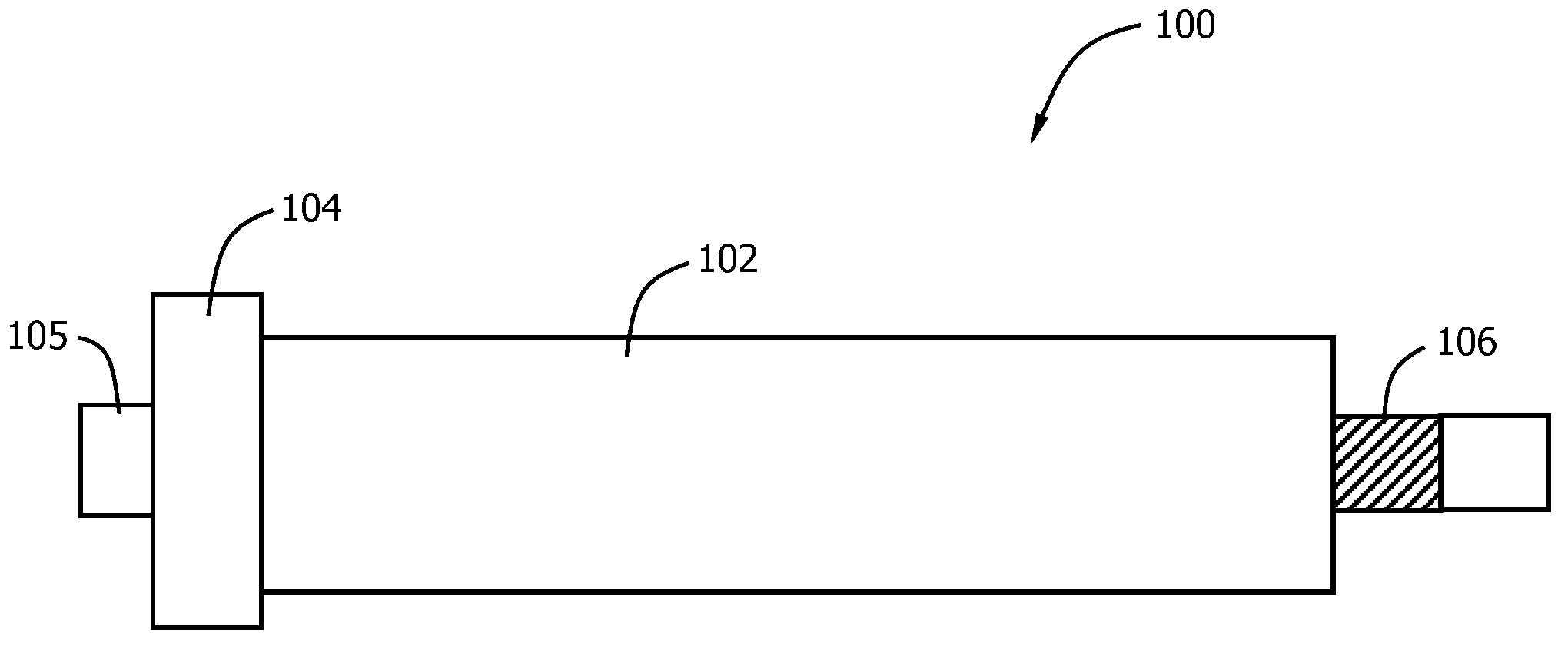
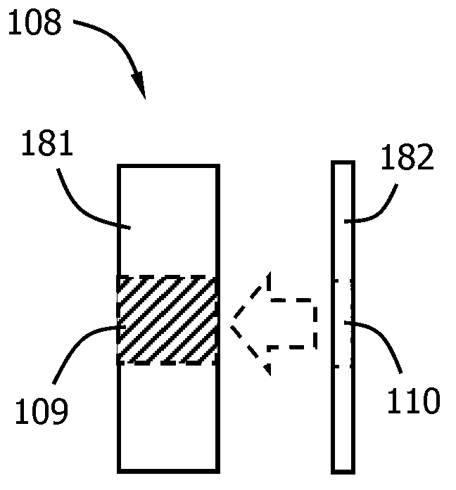
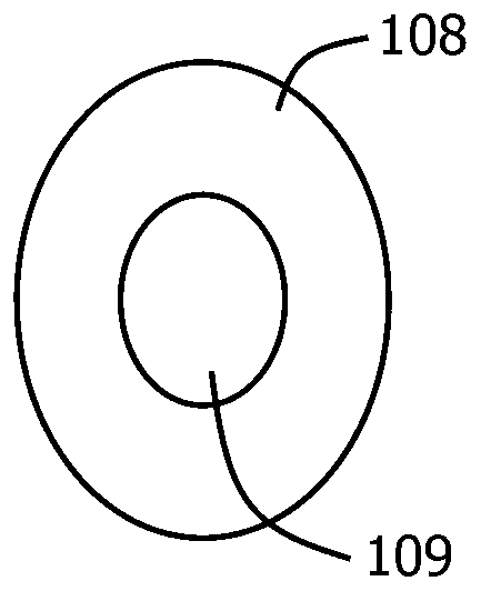
[0016] refer to figure 1 , Figure 2a and Figure 2b as shown, figure 1 , Figure 2a and Figure 2b The structure of each part in the drum according to an embodiment of the present invention is disclosed. in figure 1 revealed the structure of the barrel, Figure 2a and Figure 2b The structure of the assembly is revealed.

[0017] As shown in the figure, the roller 100 of the conveyor belt includes: a cylinder body 102 , a blocking portion 104 , a second rotating shaft 106 and an assembly 108 . The cylinder body 102 is cylindrical, and the conveyor belt is sleeved on the cylinder body 102 . The blocking portion 104 is located at a first end of the barrel 102, shown as the left end in the figure. The diameter of the blocking portion 104 is larger than that of the cylinder body 102 , and the blocking portion 104 blocks the lateral sliding of the conveyor belt sleeved on the cylinder body 102 . The blocking portion 104 extends outward to form a first rotating shaft 105...


PUM


Abstract

The invention discloses a roller of a conveyor belt. The roller comprises a barrel body, a resisting part, a second rotating shaft and an assembling component, wherein the barrel body is sleeved by the conveyor belt; the resisting part is positioned to the first end of the barrel body, and the diameter of the resisting part is larger than that of the barrel body; the resisting part is used for resisting the conveyor belt to laterally slip, and is extended to the outside to form a first rotating shaft; the second rotating is outwards extended from the second end of the barrel body, and threads are arranged on the surface of an internal section of the second rotating shaft; the surface of an external section of the second rotating is smooth; a thread hole is formed in the centre of the assembly component, and the thread hole is matched with the second rotating shaft through the diameter; the assembly component is fixed to the second rotating shaft through the threads; the external section of the second rotating shaft is extended out of the thread hole of the assembly component; the outside diameter of the assembly component is larger than the diameter of the barrel body; and the assembly component is used for resisting the conveyor belt to laterally slip. According to the roller provided by the invention, one side of the roller is a fixed structure while the other side of the roller is a dismountable structure; the conveyor belt can be simply replaced by dismounting the assembly component, and the operation is convenient to carry out.

Description

technical field [0001] The invention relates to the field of conveyors, in particular to a roller of a conveyor belt. Background technique [0002] Belt conveyor is an ideal high-efficiency continuous transportation equipment, especially suitable for continuous transportation of bulk and powder materials. Compared with other transportation equipment (such as locomotives), the belt conveyor has the advantages of long transportation distance, large transportation capacity, continuous transportation, etc., and it is reliable in operation and easy to realize automation and centralized control. [0003] Belt conveyors generally include the following main components: conveyor belts, drive rollers, tensioning devices, braking devices and cleaning devices. [0004] The conveyor belt is in the form of a ring, which is set on the driving roller and driven by the driving roller to realize the function of conveying. Commonly used conveyor belts are rubber belts and plastic belts. The...

Claims


Application Information

Patent Timeline
Patent Type & Authority Applications(China)
IPC IPC(8): B65G23/04
Inventor 朱井钟
Owner 昆山特力伯传动科技有限公司
Why Eureka
Try Eureka