Platform on upper part of large mine hydraulic excavator

A hydraulic excavator, mining technology, applied in the direction of earthmoving machine/shovel, construction, etc., can solve the problems of increasing the failure rate of hydraulic system, mechanical failure, weight increase, etc., to improve the production cost, strengthen the market value, power foot effect

Active Publication Date: 2014-07-16
TAIYUAN HEAVY IND
View PDF6 Cites 0 Cited by
  • Summary
  • Abstract
  • Description
  • Claims
  • Application Information

AI Technical Summary

Problems solved by technology

The power unit 44 is the power source of the excavator. Its motor is connected to the main pump through a reducer. In the prior art, it is driven by a single motor. The road distance increases and the layout is complicated, and the failure rate of the hydraulic system is increased
In addition, this layout method can only be driven by a single motor and a single drive, and cannot be driven by dual motors. However, due to the development of large mining hydraulic excavators, the bucket capacity, motor power, and motor displacement will increase accordingly. Large, the volume and weight of the upper platform components such as the cab base 42, cooling device 43, and power device 44 increase, making it difficult for a single motor drive to meet the power demand, so the existing technology has been severely limited
[0005] Finally, in the prior art, the facade structure of the slewing platform 4 (that is, the frame supporting the boom 11) and the bottom surface structure are set separately, and the two are connected again, which is prone to mechanical failure due to insufficient strength and affects the overall structure of the excavator. machine security
Moreover, the boom 11 is connected to the elevation structure of the slewing platform 4, the boom cylinder 12 is connected to the bottom structure of the slewing platform 4, and the boom 11 and the boom cylinder 12 are respectively located on different force-bearing surfaces. , unbalanced force, prone to failure

Method used


Image

  • Platform on upper part of large mine hydraulic excavator
  • Platform on upper part of large mine hydraulic excavator
  • Platform on upper part of large mine hydraulic excavator

Examples


Embodiment Construction

[0038] Typical embodiments embodying the features and advantages of the present invention will be described in detail in the following description. It should be understood that the present invention can have various changes in different embodiments, which do not depart from the scope of the present invention, and the descriptions and drawings therein are essentially for illustrative purposes, rather than limiting this invention.

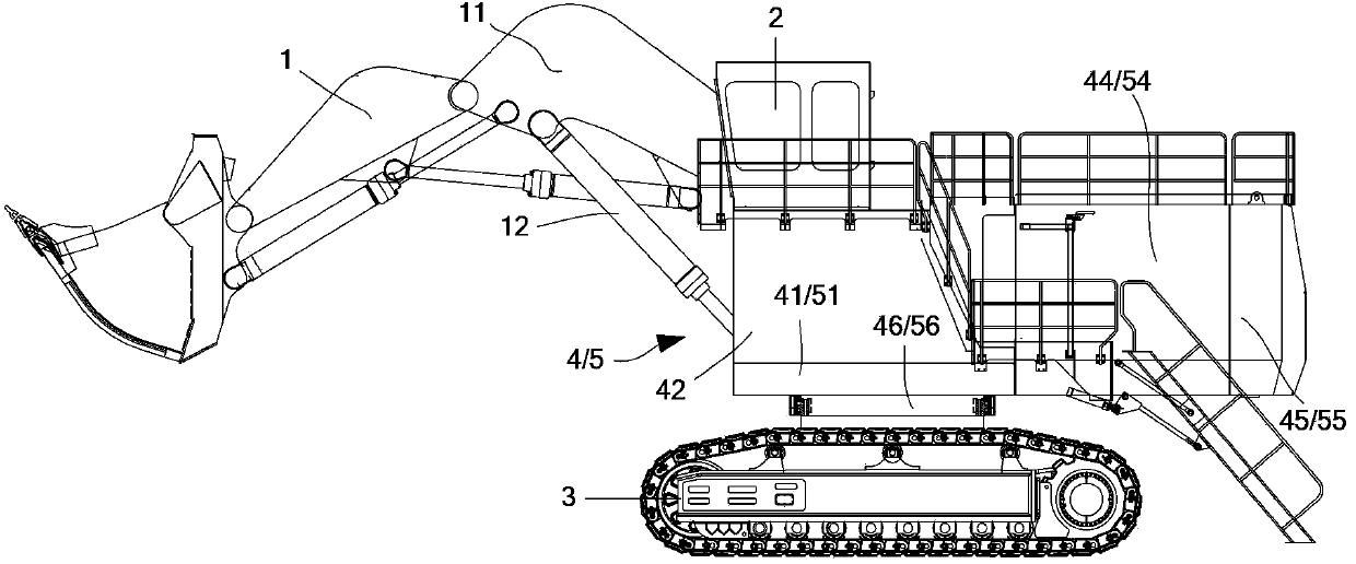
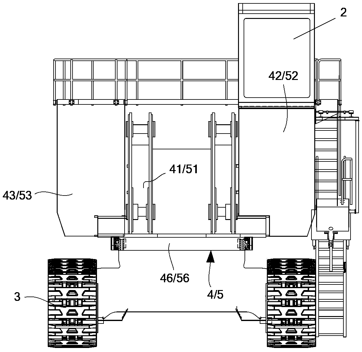
[0039] In the present invention, the structure of a large-scale mining hydraulic excavator is also figure 1 versus figure 2 As shown, it is mainly composed of a working device 1 (including a boom 11), a cab 2, a walking mechanism 3, and an upper platform 5 of the present invention.

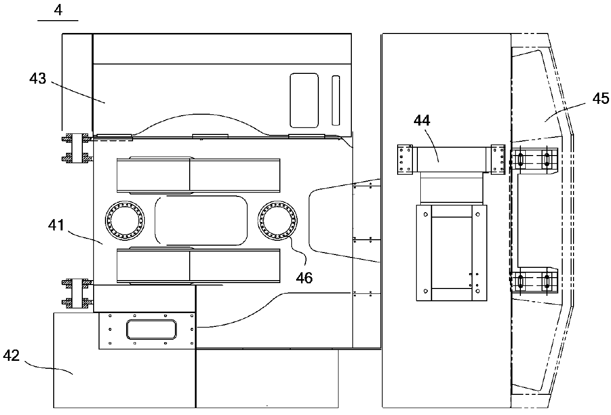
[0040] Such as Figure 4 As shown, the upper platform 5 of the present invention includes a slewing platform 51, a cab base 52, a cooling device 53, a power device 54, a counterweight 55, and a slewing support 56. Among them, the cab base 52, the cooling device 53, the powe...


PUM


Abstract

The invention discloses a platform on the upper part of a large mine hydraulic excavator. The platform comprises a revolving platform, a cab pedestal, a cooling device, a power device, a balancing weight and a revolving support; the cab pedestal, the cooling device, the power device and the balancing weight are mounted on the revolving platform; the revolving platform is rotatably arranged on an under-frame beam of an excavator through the revolving support; the revolving platform comprises a bottom plate, two box girders and two wing plates; the two box girders are welded on the bottom plate by means of transversely keeping a certain distance relatively to a vertical axial line of the bottom plate; the two wing plates are arranged on the upper part of the bottom plate, and are respectively welded at the outer sides of the two box girders. According to the platform, the revolving platform adopts the structures of the box girders to guarantee high intensity; a movable arm is connected with a movable arm cylinder through pin shafts on the box girders to balance the exerted force; the cab pedestal and the cooling device are mounted on the revolving platform through a connecting block pair and a fastener so as to achieve convenience and rapidness; and a dual-power device is adopted to keep more sufficient power.

Description

Technical field [0001] The invention relates to a large-scale mining hydraulic excavator, in particular to the structure of the upper platform of the large-scale mining hydraulic excavator. Background technique [0002] The structure of a large mining hydraulic excavator is such as figure 1 versus figure 2 As shown, it is mainly composed of a working device 1 (including a boom 11), a cab 2, a walking mechanism 3, and an upper platform 4. [0003] Such as image 3 As shown, the upper platform 4 mainly includes a slewing support 46, a slewing platform 41, a cab base 42, a cooling device 43, a power device 44, and a counterweight 45. The slewing platform 41 is rotatably mounted on the underframe beam of the excavator through the slewing support 46. The cab base 42, the cooling device 43, the power device 44 and the counterweight 45 are all installed on the revolving platform 41 and can rotate together with the revolving platform 41. Among them, the cab base 42 is arranged on the le...

Claims


Application Information

Patent Timeline
Patent Type & Authority Patents(China)
IPC IPC(8): E02F9/08
Inventor 谭磊李光
Owner TAIYUAN HEAVY IND
Why Eureka
Try Eureka