Conical cutter head of a shield machine

A shield machine and cutter head technology, which is applied in mining equipment, earthwork drilling, tunnels, etc., can solve problems such as damage in the middle of excavation, large tool consumption, and wear, so as to reduce energy consumption, improve utilization rate, and improve knife The effect of disc stiffness

Active Publication Date: 2014-10-08
NORTH CHINA ELECTRIC POWER UNIV (BAODING)
View PDF8 Cites 0 Cited by
  • Summary
  • Abstract
  • Description
  • Claims
  • Application Information

AI Technical Summary

Problems solved by technology

[0003] The invention provides a shield machine conical cutter for the deficiencies such as serious wear of the flat cutterhead of the shield machine, high consumption of cutters on it, and damage in the middle of the excavation when it encounters boulders (solitary rocks) plate

Method used


Image

  • Conical cutter head of a shield machine
  • Conical cutter head of a shield machine

Examples


Embodiment Construction

[0013] The present invention provides a conical cutter head of a shield machine, and the present invention will be further described below in conjunction with the accompanying drawings and specific embodiments.

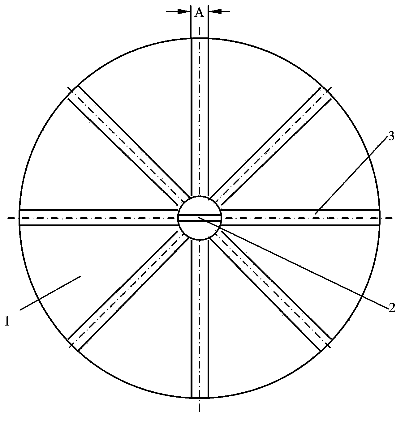
[0014] figure 1 It is the front view of the shield cutter head; figure 2 Top view of shield cutter head. The center position of cutterhead 1 is provided with shell-shaped knife rest, and shell-shaped knife 2 is installed on the shell-shaped knife-rest, and a plurality of spokes 3 with shell-shaped knife-rest as the center outward radiation are installed on the cutterhead 1; At first to the setting of each parameter will be explained:

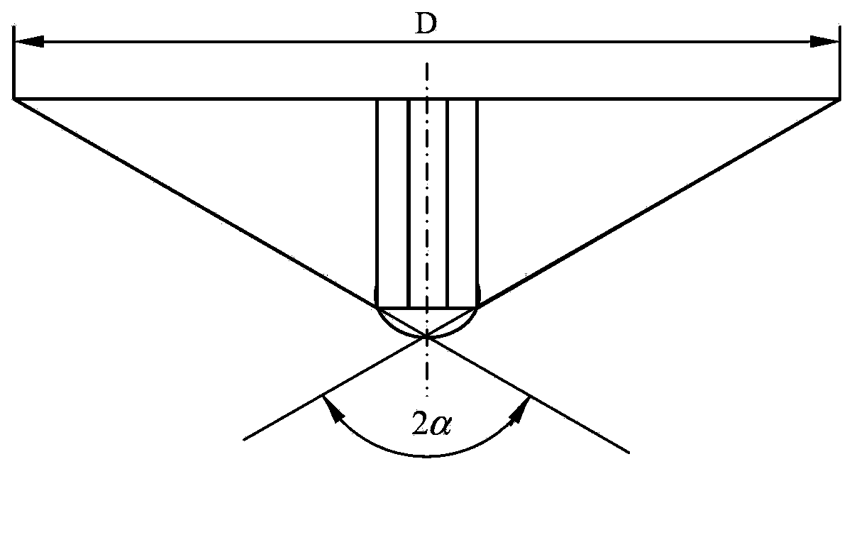
[0015] D—cutter diameter (m);

[0016] α—half angle of cone top of cone cutter head (rad);

[0017] A—spoke width (m);

[0018] f—Static friction coefficient between shield machine cutter head and rock.

[0019] The cutter head 1 , the spokes 3 and the bell-shaped cutter frame form a conical structure, and then the half-angle of ...


PUM


Abstract

The invention belongs to the technical field of design of shield tunneling machine cutters, in particular to a tapered cutter of a shield tunneling machine. The cutter, spokes and a shell-shaped tool rest form a tapered structure, and a cone-apex half angle alpha is less than or equal to arctanf, wherein alpha is the cone-apex half angle, and f is the static friction coefficient between the cutter of the shield tunneling machine and a boulder. The spokes are distributed uniformly, the number N of the spokes is an integer, A is the width of the spokes, B is less than min (L, W, H), and L, W, H are determined by geological exploration information, where L is the maximal size of the boulder above in the length direction, W is the maximal size of the boulder above in the width direction and H is the maximal size of the boulder above in the height direction. According to the scheme, the rigidity of the cutter is improved, the interaction between a tool and the boulder is lowered, and the working performance of a shield is effectively improved; furthermore, the energy consumption during boosting can be effectively reduced under the condition of the same tunneling quantity; and the working efficiency can be improved and the energy consumption can be reduced by about 5 percent respectively by preliminary estimation, so that the utilization rate of the shield tunneling machine is effectively improved.

Description

technical field [0001] The invention belongs to the technical field of shield machine cutter head design, in particular to a shield machine cone cutter head. Background technique [0002] At present, the cutterheads of the shield machine are all flat cutterheads. During use, especially when there are boulders (solitary rocks) in the stratum, there are problems such as serious wear, large consumption of cutters on it, and damage in the middle of excavation, which affect the excavation efficiency. Increased costs. Contents of the invention [0003] The invention provides a shield machine conical cutter for the deficiencies such as serious wear of the flat cutterhead of the shield machine, high consumption of cutters on it, and damage in the middle of the excavation when it encounters boulders (solitary rocks) plate. [0004] The technical scheme adopted in the present invention is: [0005] The center of the cutter head is equipped with a shell-shaped knife holder, on whi...

Claims


Application Information

Patent Timeline
Patent Type & Authority Patents(China)
IPC IPC(8): E21D9/08
Inventor 张照煌王磊李福田孟亮孙飞
Owner NORTH CHINA ELECTRIC POWER UNIV (BAODING)
Why Eureka
Try Eureka