Centrifugal compressor used for generating two different pressure ratios

A centrifugal compressor and compressor technology, which is applied to the components, mechanical equipment, machines/engines, etc. of the pumping device for elastic fluid, can solve the problems of increasing wear, reducing mechanical efficiency, and the rotor system being too long, etc. Achieve the effect of improving rotor balance, simplifying overall structure, reducing bending resistance and rigidity

Inactive Publication Date: 2012-12-26
BEIJING INSTITUTE OF TECHNOLOGYGY
View PDF7 Cites 10 Cited by
  • Summary
  • Abstract
  • Description
  • Claims
  • Application Information

AI Technical Summary

Problems solved by technology

This form makes the entire rotor system too long, which increases the unbalance of the rotor, puts forward extremely high requirements on the bending resistance and rigidity of the rotor system, increases wear and reduces mechanical efficiency, so it is necessary to use this structural form Improvements were made to combine two compressors into one

Method used


Image

  • Centrifugal compressor used for generating two different pressure ratios
  • Centrifugal compressor used for generating two different pressure ratios
  • Centrifugal compressor used for generating two different pressure ratios

Examples


Embodiment 1

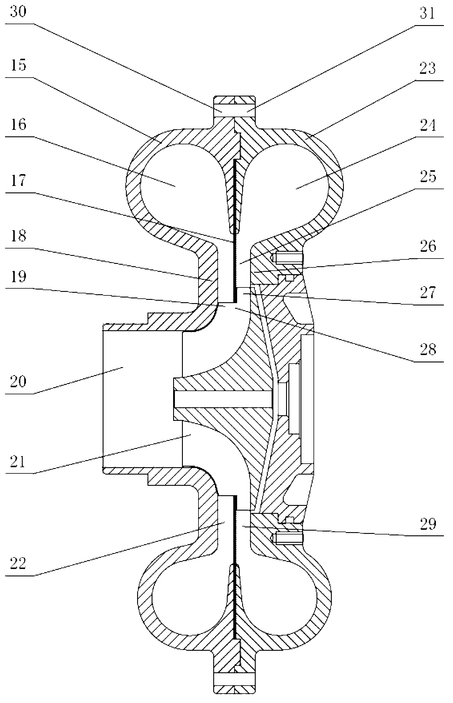
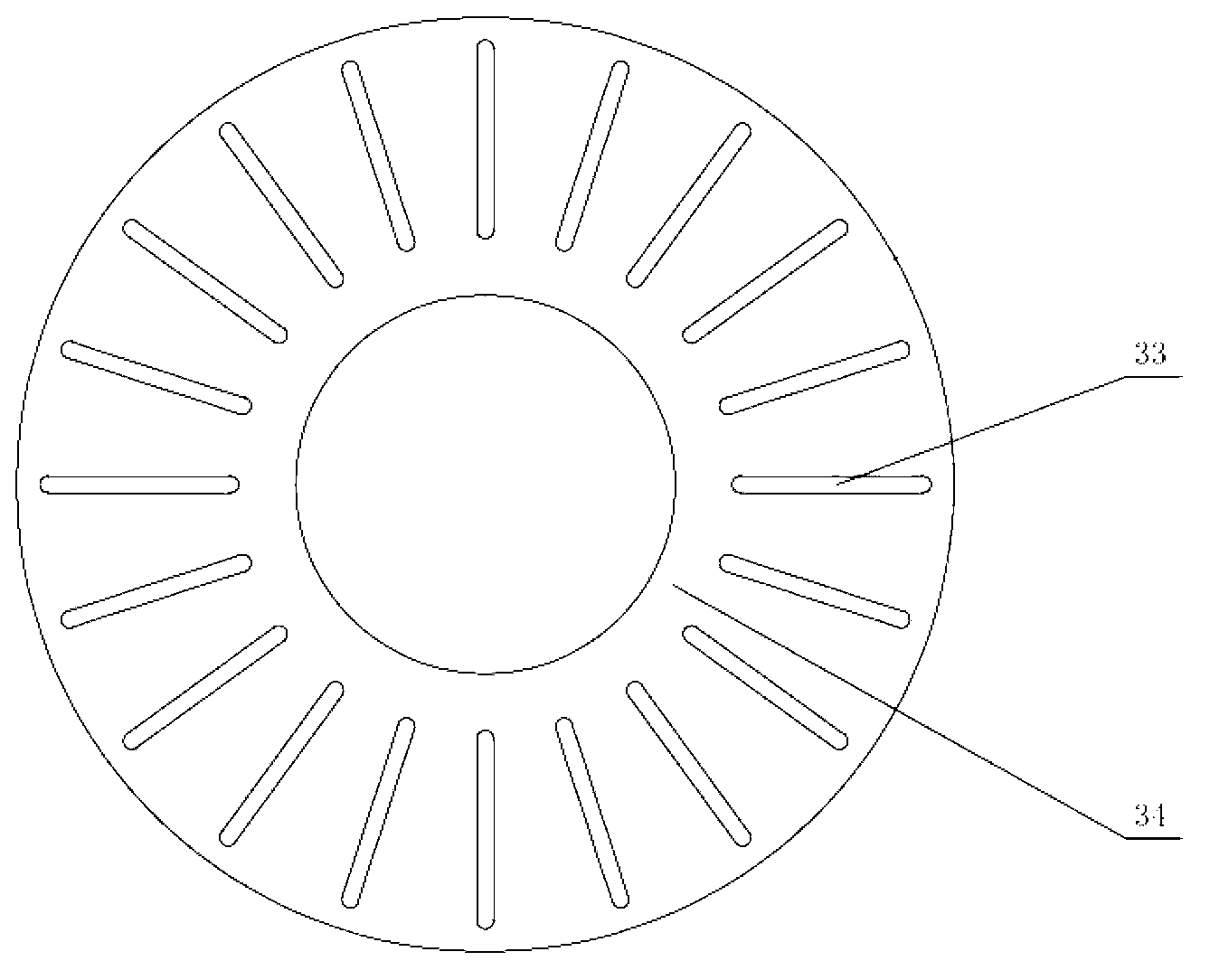
[0025] Embodiment 1: as figure 2 As shown, a centrifugal compressor device for generating two different pressure ratios includes a compressor front shell 15 , a compressor rear shell 23 , an annular plate 17 and a stepped centrifugal compressor impeller 21 . The compressor front shell 15 is provided with a compressor air inlet 20 and a compressor front collector runner volute 16; The rear casing 23 of the machine is connected by bolts, and an annular plate 17 is clamped therebetween. The part other than the clamping surface of the annular plate 17 is an annular splitter plate 34; The diffuser channel formed by the diffuser wall 26 is divided into two, forming a double-channel vaneless diffuser 25; a stepped centrifugal compressor impeller 21 is installed inside the compressor front shell 15 and the compressor rear shell 23, and the impeller outlet 28 is that big and small two kinds of diameters make the impeller outlet form step shape.

[0026] The compressor front shell 15...

Embodiment 2

[0033] Embodiment 2: as Figure 5 , Figure 6 As shown, the difference between this embodiment and Embodiment 1 is that the stepped centrifugal compressor impeller 21 is different from the impeller shape in Embodiment 1. This embodiment is opposite to Embodiment 1, and the impeller outlet is designed to have a large diameter near the end of the compressor front casing 15, and is designed to have a small diameter near the end of the compressor rear casing 23. All the other parts are identical to Example 1.

[0034] The flow of the air-flow in this embodiment is basically the same as that in Embodiment 1. The air-flow flows to the impeller outlet 28 after passing through the compressor inlet 20 and the impeller 21. The air-flow is divided into two strands, and one enters near the compressor through the front end 35 of the large-diameter impeller outlet. The front vaneless diffuser 22 at the front shell 15 end, the air flow is a high-pressure air flow; the other stream enters t...


PUM


Abstract

The invention relates to a centrifugal compressor used for generating two different pressure ratios. The centrifugal compressor belongs to the technical field of a supercharging of an internal combustion engine and comprises a front shell of a compressor, a rear shell of the compressor, an annular splitter plate and step-shaped centrifugal compressor impellers. A compressor air inlet and a compressor front air collecting runner volute are arranged on the front shell of the compressor, a compressor back air collecting runner volute is arranged on the rear shell of the compressor; the compressor front air collecting runner volute is connected with the compressor back air collecting runner volute by adopting a bolt, and the annular splitter plate is arranged between the compressor front air collecting runner volute and the compressor back air collecting runner volute; a pressure enlarging passage consisting of the compressor front air collecting runner volute and the compressor back air collecting runner volute is divided into two parts by the annular splitter plate, thereby forming a dual-runner vaneless diffuser; step shaped centrifugal compressor impellers are arranged at the inner parts of the front shell of the compressor and the rear shell of the compressor; the outlets of the impellers are provided with big and small diameters, so that the outlets of the impeller are formed to be in a ladder shape. By using one compressor, two compressed airs with different pressure ratios is generated; the centrifugal compressor is applicable to the condition required to generate the compressed air with two pressure ratios simultaneously.

Description

technical field [0001] The invention relates to a compressor device of a turbocharger for an internal combustion engine, in particular to a centrifugal compressor device for generating two different pressure ratios, and belongs to the technical field of internal combustion engine supercharging. Background technique [0002] At present, the supercharger matched to the internal combustion engine of most vehicles is a common single-stage turbocharger. When the car is driving on plains, the pressure ratio generated by the single-stage supercharger can generally meet the matching requirements of the internal combustion engine. However, when the car enters a plateau, limited by the pressure ratio, speed and flow range of the supercharger, there will be insufficient air intake of the internal combustion engine, power drop, speed increase of the supercharger, and the working point enters the non-working area. Superchargers often cannot adapt to the harsh working environment on the ...

Claims


Application Information

Patent Timeline
Patent Type & Authority Applications(China)
IPC IPC(8): F04D29/42F04D29/44F04D29/28
Inventor 祁明旭马朝臣王鹏
Owner BEIJING INSTITUTE OF TECHNOLOGYGY
Why Eureka
Try Eureka