Error detection method for complicated pupil telescopes

An error detection and telescope technology, applied in the field of space telescopes

Inactive Publication Date: 2012-12-26
SUZHOU UNIV OF SCI & TECH
View PDF5 Cites 2 Cited by
  • Summary
  • Abstract
  • Description
  • Claims
  • Application Information

AI Technical Summary

Problems solved by technology

However, when the initial error of each sub-mirror is unknown, how to select the sub-mirror with the smallest or zero error as the reference sub-mirror remains to be studied.

Method used


Image

  • Error detection method for complicated pupil telescopes
  • Error detection method for complicated pupil telescopes
  • Error detection method for complicated pupil telescopes

Examples


Embodiment 1

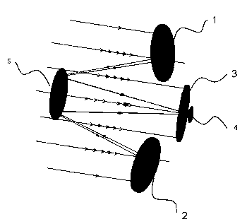
[0028] See attached figure 2 , which is a schematic structural representation of the complex pupil telescope provided by the present embodiment as a Golay3 structure complex pupil telescope; figure 2 Among them, sub-mirror 1, sub-mirror 2 and sub-mirror 3 are all spherical surfaces, they are equal in size and evenly distributed on the main mirror surface, the surface shape centers of the three sub-mirrors are respectively 120° rotationally symmetrical about the main mirror surface shape center, and the receiving surface 4 is used for The imaging of the receiving telescope, in order to eliminate the aberration, the secondary mirror 5 is an aspheric surface. This structure can be obtained by replacing the primary mirror in the double-mirror telescope with the complex pupil of Golay3. The structural parameters of the telescope are shown in Table 1.

[0029] Table 1. Golay3 complex pupil telescope structure parameters

[0030]

[0031] See attached image 3 , which is the ...

Embodiment 2

[0047] The Golay3 complex pupil telescope and target object provided by Embodiment 1 are adopted. Let the errors of sub-mirror 1, sub-mirror 2 and sub-mirror 3 be 0 respectively, and the tilt error is 3.15×10 -4 rad, tilt error 6.30×10 -4 rad.

[0048] See attached figure 1 According to step S101, each sub-mirror with different errors of the Golay3 complex pupil telescope is used to image the target separately;

[0049] According to step S102, the imaging result map obtained in step S101 is processed by computer to obtain the target grayscale image of each sub-mirror; for the results, see the attached Figure 6 , Figure 6 Among them, D, E and F diagrams are respectively the sub-mirrors 1, 2 and 3 in the Goaly3 complex pupil telescope of this embodiment sequentially image grayscale images of the target object, and the image matrix resolution M×N is 328×328, respectively The pixel values ​​of some of the above three images are shown in Table 6-Table 8.

[0050] Table 6. W...


PUM


Abstract

The invention discloses an error detection method for complicated pupil telescopes. With the same image as a target object, each sub-lens in a complicated pupil telescope separately images the target object, and the grayscale image of the target object and each sub-lens-imaged grayscale image of the target object are obtained; the corresponding pixel gray values of the grayscale image of the target object and each sub-lens-imaged grayscale image of the target object are compared, the arithmetic mean value standard variations of the pixel gray values are calculated, a reference sub-lens is determined according to the minimum arithmetic mean value standard variation, and the phase diversity method is adopted to detect the error of each sub-lens of the complicated pupil telescope. Aimed at complicated pupil telescopes with different structural forms, the error detection method can accurately determine the sub-lens with minimum error or without error as the reference sub-lens for error detection in real time according to different sub-lens errors introduced into the processes of installation, adjustment and operation of the telescope sub-lens, consequently, a better initial condition can be offered to remaining sub-lens error calculation, and the precision of detecting the errors of the sub-lenses in the complicated pupil telescope can be effectively increased; and the error detection method has the characteristics of simplicity, practicability and real-timeness.

Description

technical field [0001] The invention relates to an error detection technology for complex pupil telescopes, in particular to a method for determining a reference sub-mirror suitable for error detection of complex pupil telescopes, and belongs to the technical field of space telescopes. Background technique [0002] High-resolution space telescopes require large-aperture optical systems, but materials, manufacturing, technology, and launch all restrict the development of large-aperture optical systems. The complex pupil optical system is used in the design of space telescopes, which overcomes the problems in the design, manufacture and launch of large-aperture optical systems. Space telescopes usually adopt a double-reflection structure, mainly including a primary mirror and a secondary mirror, both of which can be spherical or aspheric, while a complex pupil telescope usually replaces the primary mirror with a small optical aperture in a specific arrangement to ensure the an...

Claims


Application Information

Patent Timeline
Patent Type & Authority Applications(China)
IPC IPC(8): G01M11/02
Inventor 范君柳吴泉英王军钱霖唐运海
Owner SUZHOU UNIV OF SCI & TECH
Why Eureka
Try Eureka