Sampling circuit and electronic equipment

A sampling circuit and circuit technology, applied in the field of circuits, can solve problems such as the complexity of the sampling circuit design, and achieve the effect of simplifying the sampling circuit and avoiding damage

Active Publication Date: 2012-12-26
HISENSE VISUAL TECH CO LTD
View PDF8 Cites 1 Cited by
  • Summary
  • Abstract
  • Description
  • Claims
  • Application Information

AI Technical Summary

Problems solved by technology

[0009] The invention provides a sampling circuit and an electronic device, which are used to solve the technical problem of complex sampling circuit design in the prior art

Method used


Image

  • Sampling circuit and electronic equipment
  • Sampling circuit and electronic equipment
  • Sampling circuit and electronic equipment

Examples


Embodiment 1

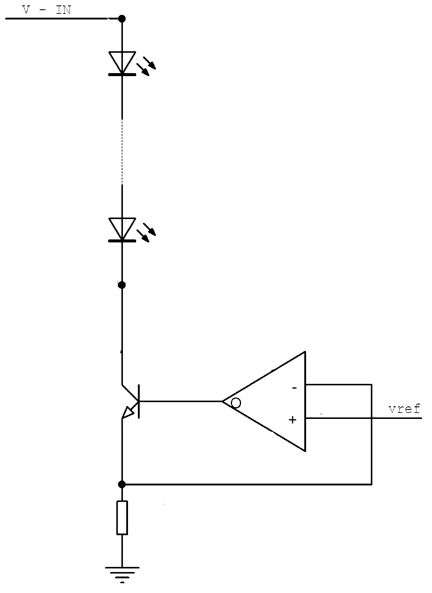
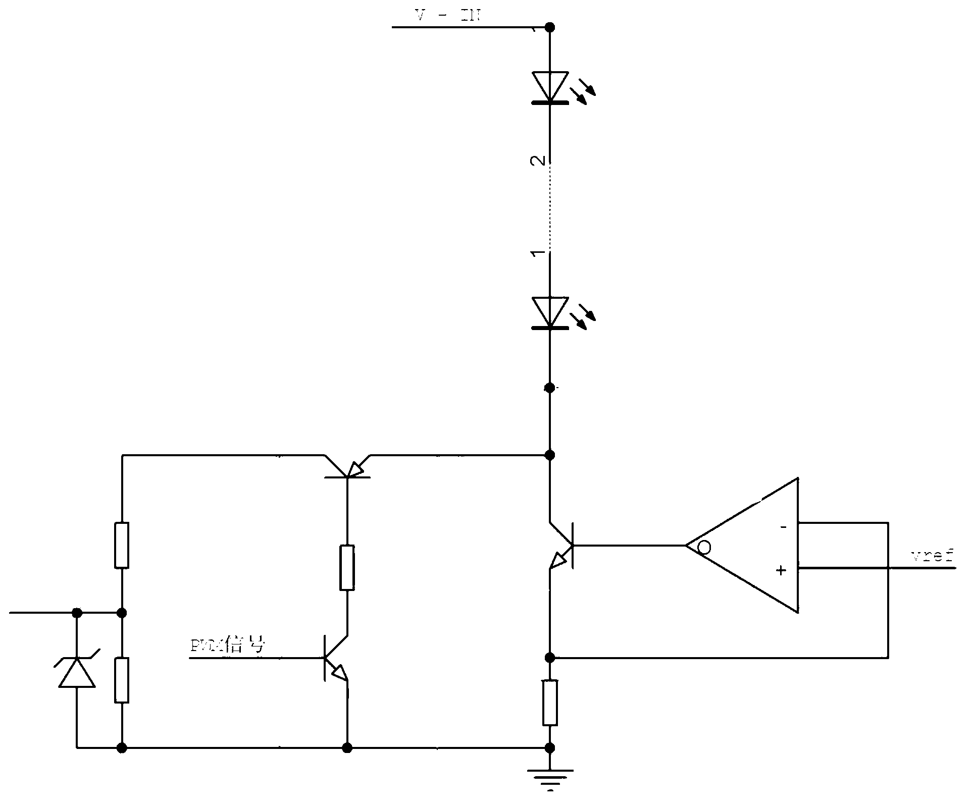
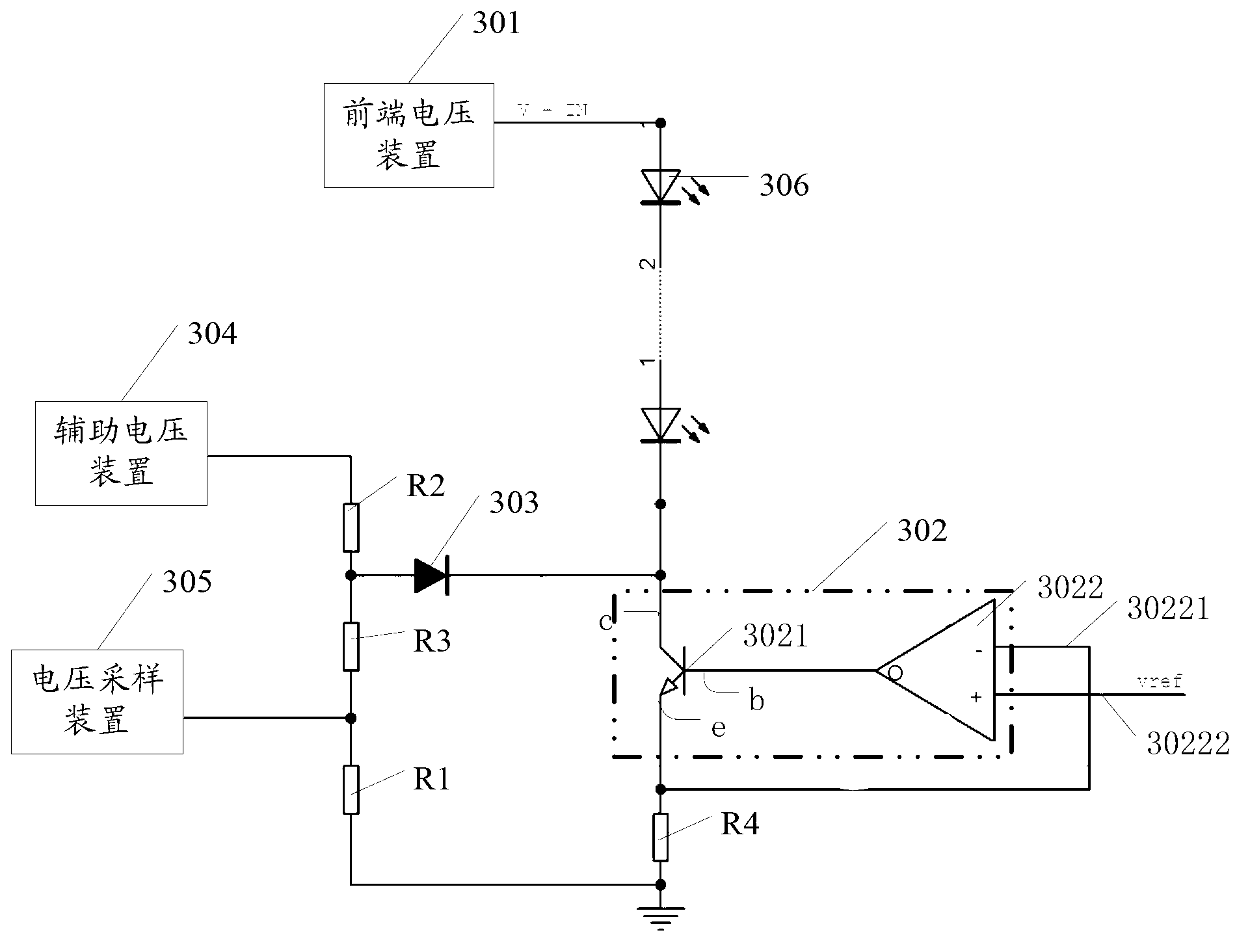
[0028] In the embodiment of this application, a sampling circuit is described, which is designed for relatively complex sampling circuits and interference, and the sampling circuit has multiple functional devices, such as image 3 Shown, first describe the specific structure of the sampling circuit.

[0029] First, the sampling circuit includes a front-end voltage device 301 , and the front-end voltage device 301 has a first voltage V-IN.

[0030] Further, the sampling circuit also includes:

[0031] The constant current source device 302 includes a voltage amplifier 3021 and an operational amplifier 3022 .

[0032] Wherein, the first end of the voltage amplifier 3021 is connected to the output end of the operational amplifier 3022 , and the second end of the voltage amplifier 3021 is connected to the output end of the front-end voltage device 301 .

[0033] However, the operational amplifier also has a first input 30221 and a second input 30222 .

[0034] In practical appl...

Embodiment 2

[0092] The embodiment of the present application describes an electronic device, which may be a TV, and the TV includes the sampling circuit described in the first embodiment above.

[0093] Through one or more embodiments of the present invention, the following technical effects can be achieved:

[0094] Through one or more embodiments of the present invention, a combination of a diode, a first resistor, and an auxiliary voltage device is used, and by comparing the characteristics of the diode and comparing the second voltage with the voltage value of the second terminal of the voltage amplifier, it is possible to realize It is used to characterize the complete sampling of the voltage value of the second terminal of the voltage amplifier, and the circuit design is simple.

[0095] Further, due to the characteristics of the diode, even when the voltage value of the second terminal of the voltage amplifier rises sharply, it will not affect the loop in the voltage acquisition de...


PUM


Abstract

The invention discloses a sampling circuit and electronic equipment. The sampling circuit comprises a constant current source device, a diode, an auxiliary voltage device, a first resistor and a voltage sampling device, wherein the constant current source device comprises a voltage amplifier and an operational amplifier, one end of the first voltage amplifier is connected with the output end of the operational amplifier, and the second end of the voltage amplifier is connected with the output end of a front-end voltage device; the cathode of the diode is connected between the second end of the voltage amplifier and the output end of the front-end voltage device; the auxiliary voltage device is connected with the anode of the diode; the first end of the first resistor is connected between the auxiliary voltage device and the anode of the diode, and the second end of the first resistor and the third end of the voltage amplifier are respectively connected with the first input end of the operational amplifier and simultaneously grounded; and the first end of the voltage sampling device is connected between the auxiliary voltage device and the anode of the diode and is connected with the first end of the first resistor.

Description

technical field [0001] The invention relates to the field of circuits, in particular to a sampling circuit and an electronic device. Background technique [0002] SG3D TV currently still occupies a certain share in the market, and the backlight control circuit in SG3D TV has more functions, so the cost of backlight control circuit in SG3D TV is often higher than that of PR3D TV and 2D TV. This has also become a competitive weakness for SG TV. In order to reduce the cost of the backlight control circuit, it is generally accepted that digital chips are used to complete the scanning logic control and the constant current control of the LED light source. [0003] Such as figure 1 as shown, figure 1 There is a constant current source device composed of a triode and an amplifier, wherein the collector in the triode is connected to the LED light source, the LED light source is powered by receiving V-IN, and the base of the triode is connected to the output end of the constant cu...

Claims


Application Information

Patent Timeline
Patent Type & Authority Applications(China)
IPC IPC(8): G01R19/25G01R15/14G01R15/04
Inventor 庞震华孟献策滕强
Owner HISENSE VISUAL TECH CO LTD
Why Eureka
Try Eureka