Rivet setter

A technology of assembler and rivet, which is applied in transportation and packaging, spring/shock absorber, vibration suppression adjustment, etc., can solve undisclosed problems, achieve the effect of reducing cycle time and suppressing impact

Inactive Publication Date: 2014-11-05
FCC KK
View PDF8 Cites 0 Cited by
  • Summary
  • Abstract
  • Description
  • Claims
  • Application Information

AI Technical Summary

Problems solved by technology

Because this technology of the prior art is not a known invention disclosed in any document, no such information is disclosed in the prior art document

Method used


Image

  • Rivet setter
  • Rivet setter
  • Rivet setter

Examples


Embodiment Construction

[0032] Preferred embodiments of the present invention will be described with reference to the accompanying drawings.

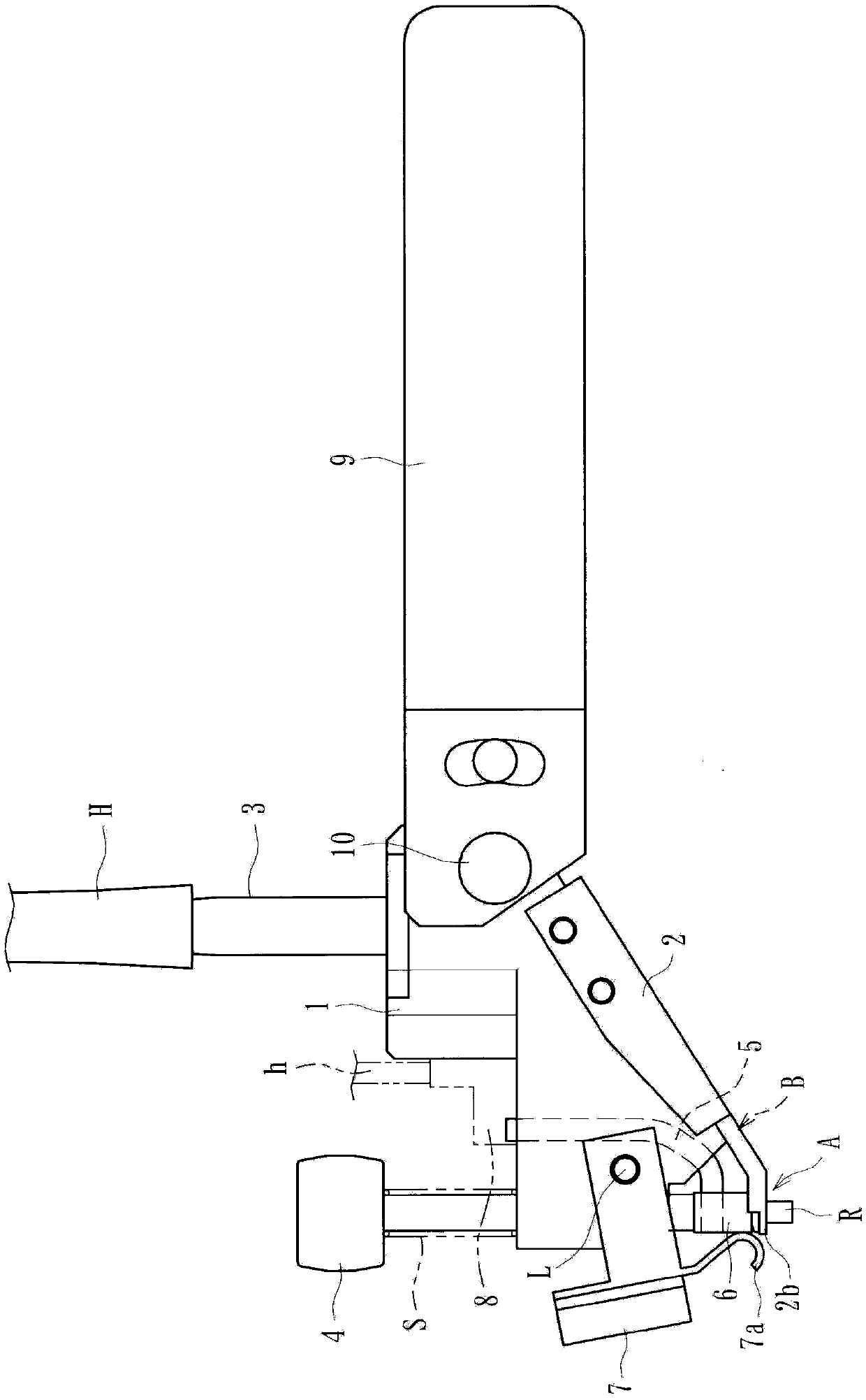
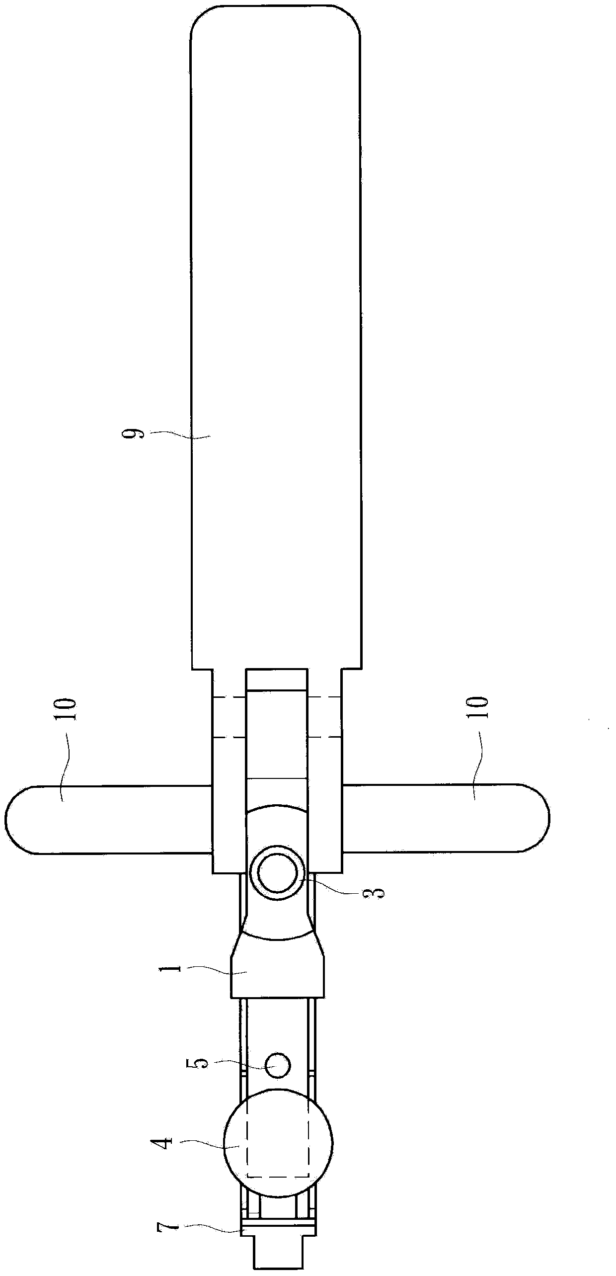
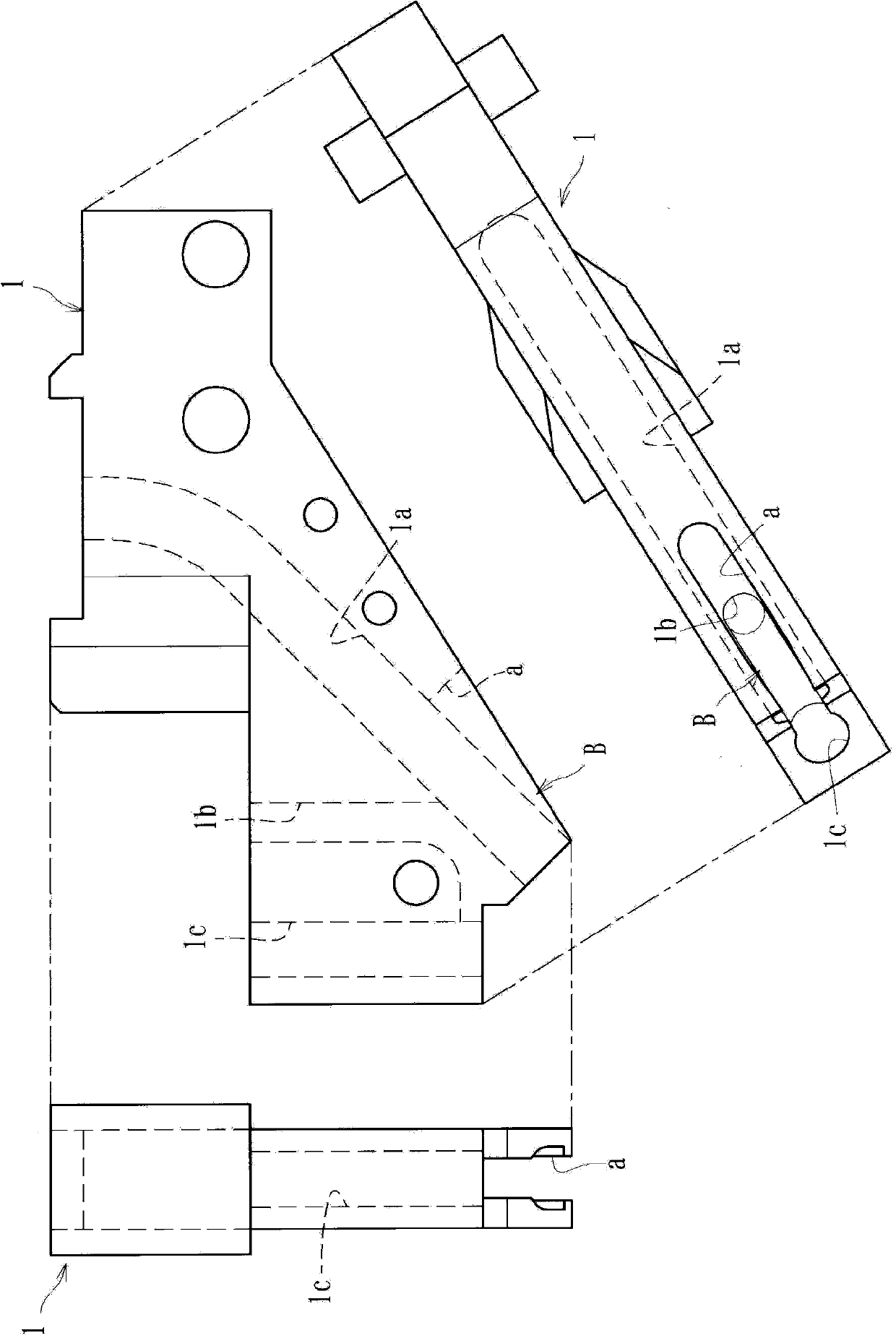
[0033] The rivet setter of the present invention is intended to assemble rivets sequentially supplied from a rivet supply device by inserting rivets into holes formed in workpieces, and mainly includes such as Figures 1 to 5 Shown are a main body 1 , a mounting member 2 , an operation button 4 , a pressing member 7 , and a detection sensor 8 .

[0034] In the illustrated embodiment, a torque damper device (lock-up clutch device) W as an example of a workpiece to which a rivet R is assembled is in Figure 13 is shown in . If the rivet R is assembled and punched, any other workpiece can be used. The torque damper device W is used to connect the torque converter case and the turbine, and includes a main body Wa holding a plurality of damper springs Wr at its outer periphery, and a pressing plate D for pressing the damper springs Wr.

[0035] Furthermore, the ...


PUM


Abstract

A rivet setter that can efficiently and smoothly perform, and reduce the takt time for a rivet setting operation. The rivet setter can be configured to set a rivet sequentially fed from a rivet supplying means by inserting the rivet into apertures formed at predetermined positions on workpieces. The rivet setter can have delivery paths for delivering the rivet one by one by sliding the rivet down to a settable position and can have a hanging support portion formed in the settable position in the tip end of the delivery path for supporting the head of rivet and for hanging the rivet shank downward. The rivet setter can be configured to enable the rivet to be set in the apertures of the workpieces by moving the hanging support portion substantially horizontally while keeping the rivet suspended in the hanging support portion and inserted into the apertures of the workpieces.

Description

technical field [0001] The present invention relates to a rivet setter that assembles rivets sequentially supplied one by one from a rivet supply device by inserting the rivets into holes formed at predetermined positions on a workpiece. Background technique [0002] A related art rivet setter for assembling a rivet by inserting the rivet into a hole formed at a predetermined position of a workpiece is configured such that it is connected to a rivet supply device via a hose, and the rivet is loaded from the rivet supply device by compressed air. Sequentially supply one by one. The rivet setter can be operated by being held by an operator and includes: a conveying path for conveying the rivets to a mountable position; engaging claws for engaging heads of supplied rivets to mountable positions Fitting position and making the shank of the rivet (the part of the rivet formed continuously with the head so as to be caulked) protrude to the outside; and a depressing member for the...

Claims


Application Information

Patent Timeline
Patent Type & Authority Patents(China)
IPC IPC(8): B21J15/32B65G47/14
CPCB21J15/14B21J15/32F16F15/1203Y10T29/49954Y10T29/49956Y10T29/5118Y10T29/53487Y10T29/53513Y10T29/53522Y10T29/5377
Inventor 菊池庸隆
Owner FCC KK
Why Eureka
Try Eureka