Pneumatic vehicle tyre

A technology for pneumatic tires and vehicles, applied in the reinforcement layer of pneumatic tires, heavy-duty tires, heavy-duty vehicles, etc., can solve the problems of high structure density, adverse effects of wear, and many materials, and achieve good friction, high puncture resistance and The effect of durability, enhanced puncture resistance and high durability

Active Publication Date: 2012-12-26
CONTINENTAL REIFEN DEUTSCHLAND GMBH
View PDF5 Cites 4 Cited by
  • Summary
  • Abstract
  • Description
  • Claims
  • Application Information

AI Technical Summary

Problems solved by technology

Even with steel cords having a large cross-sectional thickness, the higher density of this arrangement (necessary to limit the risk of punctures) necessarily results in a belt ply that is heavy, material-intensive and has a detrimental effect on wear

Method used


Image

  • Pneumatic vehicle tyre
  • Pneumatic vehicle tyre
  • Pneumatic vehicle tyre

Examples


Embodiment Construction

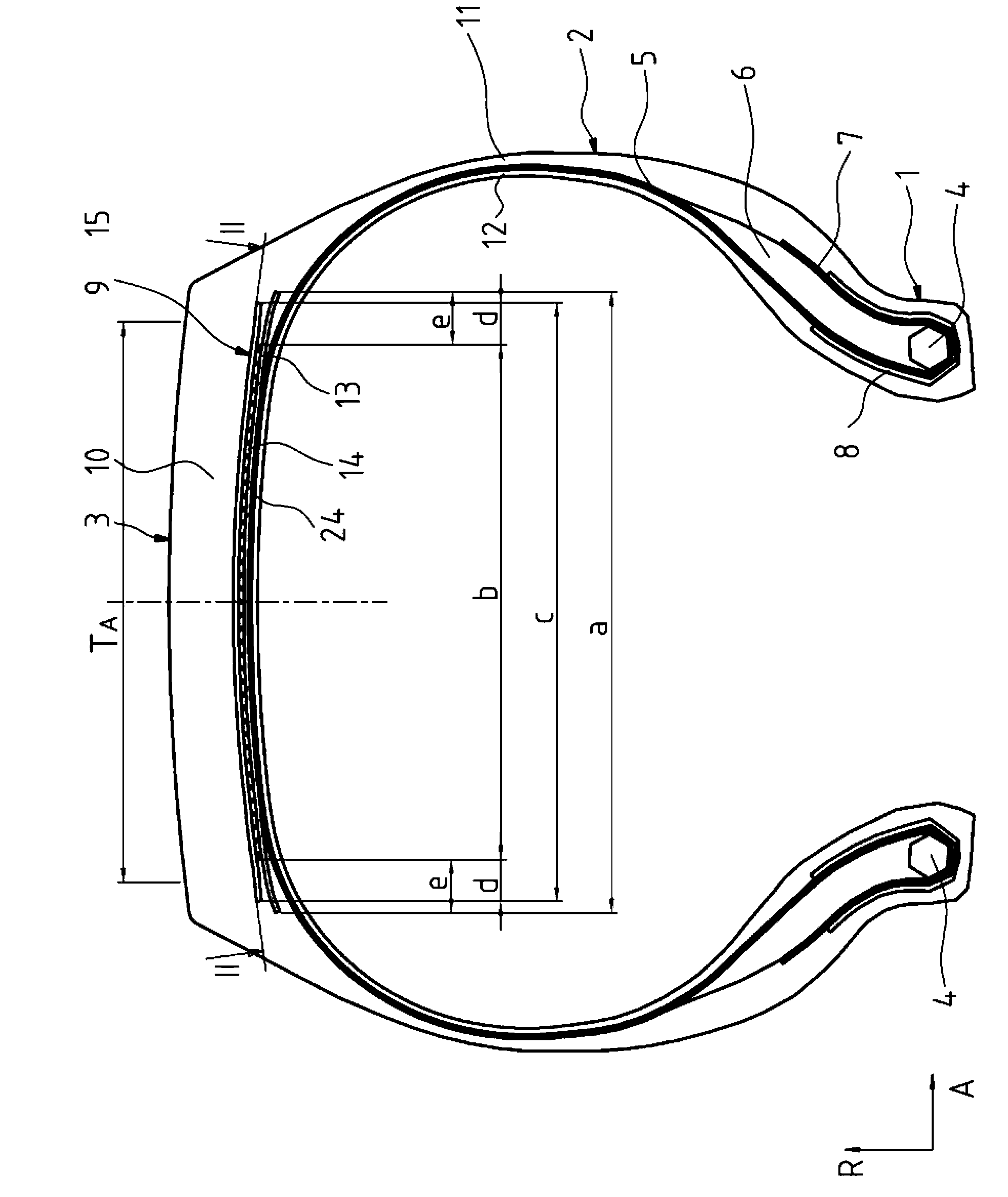
[0051] figure 1 with figure 2 Shown is a commercial vehicle pneumatic tire of radial configuration type with two sidewalls 2 extending in the radial direction R of the vehicle tire, and a Crown area 3. In this case the side walls 2 are designed at the end of their extension directed inwards in the radial direction R with a bead region 1 in which a bead core 4 of a known type is formed, The bead core is stretch-resistant in the circumferential direction U and extends over the circumference of the tire in the circumferential direction U. The bead cores 4 are designed by winding in a known manner steel wires extending in the circumferential direction U of the vehicle pneumatic tire and embedded in rubber. An apex (bead filler) 6 of triangular cross-section, made of a hard rubber material, is formed on the bead cores 4 in a conventional manner. The vehicle pneumatic tire is designed with a carcass 5 extending outwardly in the radial direction R of the vehicle pneumatic tire ...


PUM


Abstract

A pneumatic vehicle tyre for commercial vehicles, comprising a carcass (5), a breaker belt (9) built up radially outside the carcass (5) and a profiled tread rubber (10) built up on the breaker belt (9) radially outside the breaker belt (9), wherein the breaker belt (9) is formed by at least three belt plies (13, 14, 15) arranged lying one on top of the other from the inside outwards in the radial sense wherein the radially inner belt ply (13) and the radially outer belt ply (15) are working plies, with steel reinforcing elements (23, 25) embedded in rubber and arranged at an angle in relation to the circumferential direction of 10°-45°, and wherein the belt ply (14) arranged between these two working plies (13, 15) is a belt ply (14) formed as a zero degree ply with parallel reinforcing elements (24), which are embedded in rubber and in their alignment include an angle β in relation to the circumferential direction U where 0°≰β≰5°, wherein the reinforcing elements (23, 25) of the two working plies (13, 15) each have a fracture force F where F>1800 N and at 10% of the fracture force an elongation D of 0.22%≰D≰0.4%.

Description

technical field [0001] The present invention relates to a vehicle pneumatic tire, in particular for commercial vehicles, having a carcass, with a belt established radially outside the carcass, and with a A shaped tread built outwardly on the belt formed of at least three belt plies arranged one above the other from radially inner to radially outer position, the radially inner belt ply and the radially outer belt ply are working plies with parallel steel reinforcements embedded in rubber, the radial The reinforcements of the inner belt ply form an angle α with respect to the circumferential direction U in their orientation, 10° ≤ α ≤ 45°, and the reinforcements of the radially outer belt ply with respect to the circumferential The directions U form an angle γ, 10° ≤ γ ≤ 45°, and the reinforcements of one working ply have an inverse and the belt ply arranged between the two working plies is a belt ply which is designed as a zero-degree ply and has parallel reinforcing These r...

Claims


Application Information

Patent Timeline
Patent Type & Authority Applications(China)
IPC IPC(8): B60C9/20B60C9/22
CPCB60C9/2006B60C2200/06B60C2009/209B60C2009/208B60C9/22B60C9/20B60C2009/2012B60C2009/2074B60C2009/2214
Inventor 特蕾西娅·贝克尔迈克·舒尔特克里斯托夫·拜代尔瑙
Owner CONTINENTAL REIFEN DEUTSCHLAND GMBH
Why Eureka
Try Eureka