Supercharge Your Innovation With Domain-Expert AI Agents!

Device for supplying fluid to a continuously variable transmission

A continuously variable transmission, transmission technology, applied in mechanical equipment, components with teeth, transmissions, etc., can solve problems such as energy use

Active Publication Date: 2016-03-30
ALLISON TRANSMISSION INC
View PDF5 Cites 0 Cited by
  • Summary
  • Abstract
  • Description
  • Claims
  • Application Information

AI Technical Summary

Problems solved by technology

However, operating a single pump at the pressures required by the variator and clutches and at the high flow rates required for lubrication results in the use of unnecessary energy

Method used


Image

  • Device for supplying fluid to a continuously variable transmission
  • Device for supplying fluid to a continuously variable transmission
  • Device for supplying fluid to a continuously variable transmission

Examples


Embodiment Construction

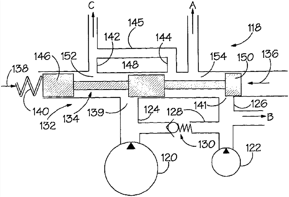
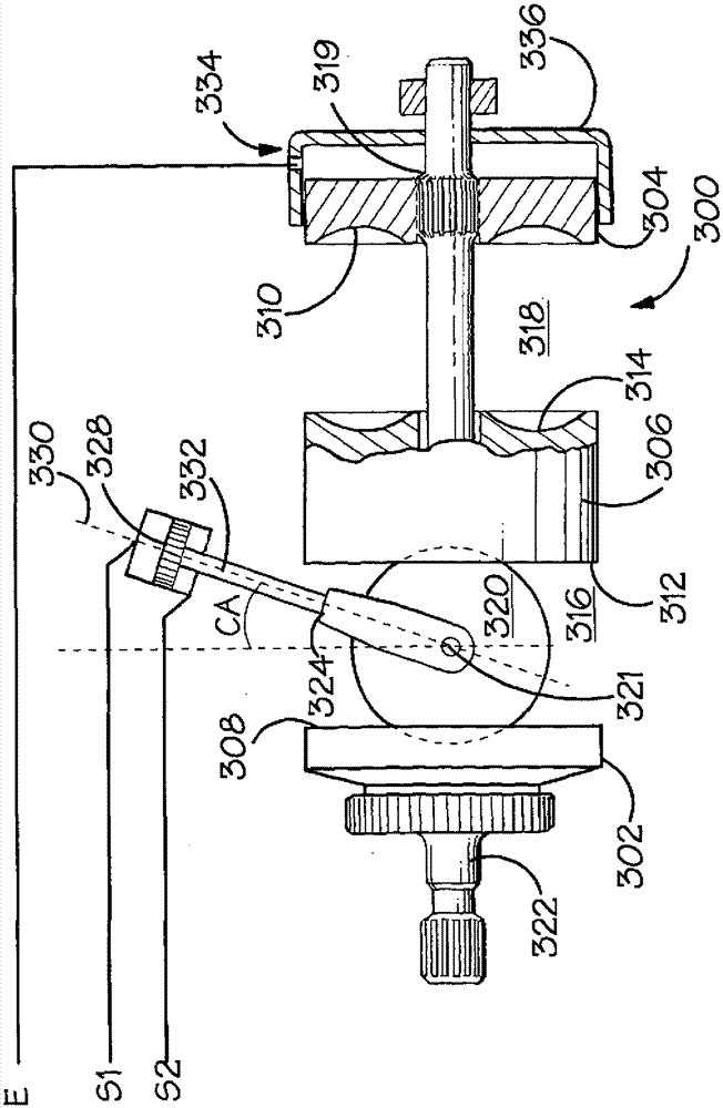
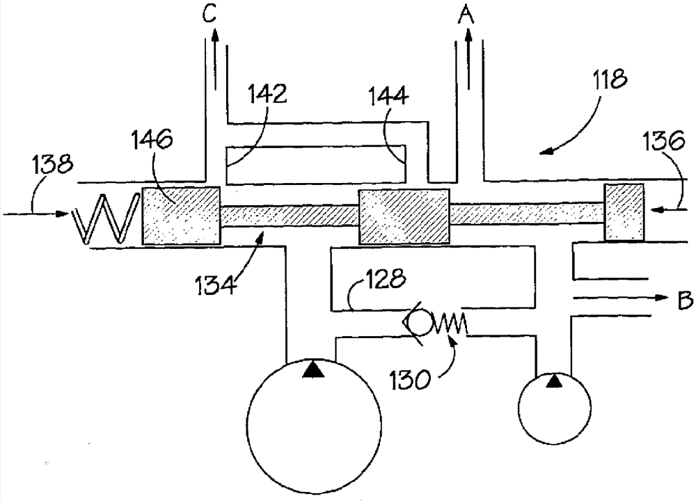
[0029] figure 1 The converter 300 represented in is known in the art and is given here for completeness and because its mode of operation creates some technical challenges addressed by the present invention. Note however that this is given by way of example and not limitation. The invention can be implemented in transmissions employing other types of variators. The variator 300 is a toroidal race rolling traction type with coaxially mounted input races 302 , 304 on either side of a central output race 306 . The face 308 , 310 of each input race is semi-annularly recessed and directed towards a similarly recessed face 312 , 314 of the output race respectively, thereby defining two generally annular cavities 316 , 318 accommodating the drum 320 . Only one roller is shown, but actual transducers typically have two or three such rollers spaced at circumferential intervals around each cavity 316 , 318 . The races are mounted on the variator shaft 322 to which the input races 302...


PUM


Abstract

An apparatus for supplying fluid to a continuously variable transmission having a lubrication system and at least one transmission control system is disclosed. The apparatus includes a first pump and a second pump (120, 122). The first pump has an output connectable to the lubrication system through a supply control valve arrangement (132). The second pump has an output connectable to the transmission control system. The device has a delivery channel (128) through which the first pump can be connected to the transmission control system. The supply control valve structure is adapted to selectively throttle the fluid supply from the output of the first pump to the lubrication system such that fluid output from the first pump is diverted through the transfer passage to the transmission control system.

Description

technical field [0001] The present invention relates to an arrangement for supplying fluid to a continuously variable transmission. Background technique [0002] Continuously variable transmissions (hereinafter abbreviated "CVTs") typically incorporate: [0003] i. Inverter, A variator is a device having a rotary input and a rotary output, and is designed to transmit drive between the two at a continuously variable variator ratio (the ratio of the variator input speed to its output speed) mechanism. [0004] ii. The associated gear train by which the variator is coupled at the transmission input (for example to a drive such as an engine) and at the transmission output (which may for example be a drive shaft coupled to the driven wheels of a motor vehicle) between. Due to the gear train, the variator ratio governs the variator (the ratio of the input speed of the variator to its output speed) but need not be equal to the variator; and [0005] iii. A clutch structure inco...

Claims


Application Information

Patent Timeline
Patent Type & Authority Patents(China)
IPC IPC(8): F16H57/04F16H61/00
CPCF16H15/38F16H57/0441F16H57/0446F16H57/049F16H61/0025F16H2061/0037Y10T137/86131F16H61/0021F16H61/66F16K11/0712
Inventor J.W.E.富勒
Owner ALLISON TRANSMISSION INC
Features
  • R&D
  • Intellectual Property
  • Life Sciences
  • Materials
  • Tech Scout
  • Unparalleled Data Quality
  • Higher Quality Content
  • 60% Fewer Hallucinations
Learn More