Power converting apparatus
A technology for power conversion and equipment, applied in the field of suppressing sudden current changes to prevent high impact voltage from being applied to switching elements, achieving the effect of reducing the amount of change and preventing impact voltage
- Summary
- Abstract
- Description
- Claims
- Application Information
AI Technical Summary
Problems solved by technology
Method used
Image
Examples
no. 1 example
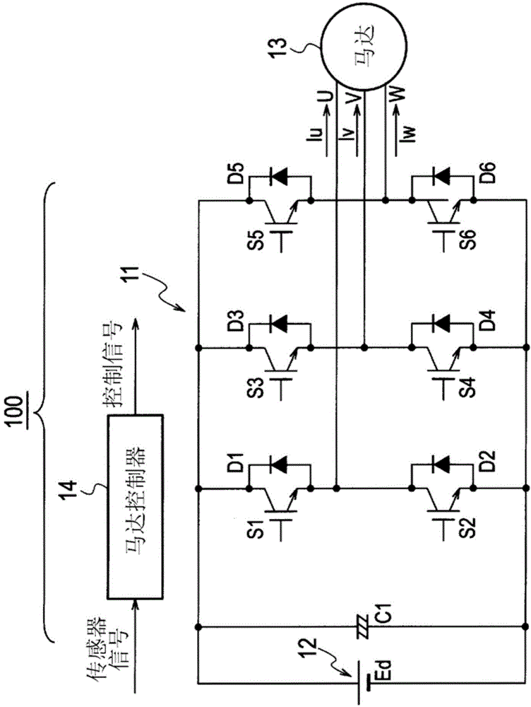
[0041] Will refer to figure 1 The structure of the power conversion device 100 according to the first embodiment of the present invention and the motor 13 driven by the power supplied from the power conversion device 100 will be described. The present embodiment is an example of a power conversion device 100 for converting DC to three-phase AC. However, the converted AC is not limited to three-phase AC, and may be a multi-phase AC of four or more phases.
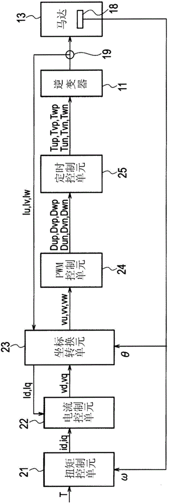
[0042] Such as figure 1 As shown, the power conversion device 100 includes an inverter 11 and a motor controller (control unit, control part) 14.
[0043] The inverter 11 includes a DC power source 12 and a capacitor C1 connected to the DC power source 12. The inverter 11 also includes: switching elements S1, S2, S3, S4, S5, and S6 using IGBTs (Insulated Gate Bipolar Transistors); and diodes D1, D2, and S1 connected in anti-parallel to the switching elements S1 to S6. D3, D4, D5 and D6. The three pairs of switching elements ...
no. 2 example
[0101] Next, the power conversion device 100 according to the second embodiment of the present invention will be explained. According to the above-mentioned first embodiment, the U-phase, V-phase, and W-phase each include a system of switching elements. On the other hand, the power conversion apparatus according to the second embodiment includes switching elements of two or more systems that are respectively connected in parallel to a common bus and drive currents for each phase. More specifically, the power conversion equipment includes switching elements of multiple systems for each phase, that is, in Figure 18 In the case of including three systems for one phase and in Figure 19 In the case of, there are four systems for one phase, and the on / off of the driving pulses used to drive the switching elements of each system in each phase is shifted to prevent current changes. Figure 18 It is an example of using an inverter circuit including three systems for each of the three p...
no. 3 example
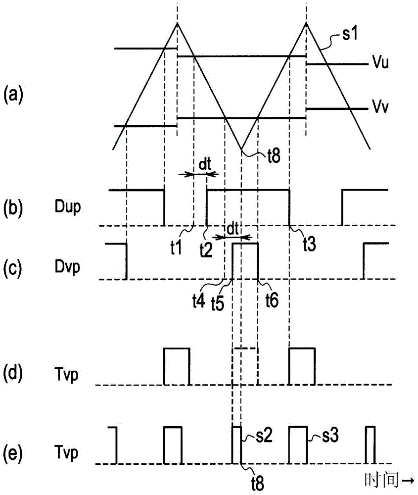
[0109] Next, the power conversion apparatus 100 according to the third embodiment of the present invention will be explained. As above image 3 As shown in (e), one drive pulse is divided into a plurality of drive pulses (for example, two drive pulses), and then the timing of one of these drive pulses is synchronized with the timing of the other drive pulse, thereby suppressing current changes.
[0110] When the drive pulse is shifted, the synchronization of the continuous timing between the phases or in the same phase becomes complicated. Thus, it may be difficult to synchronize the time when one phase (for example, the U phase) is turned off with the time when the other phase (for example, the W phase) is turned on. Consider the situation. Such as Figure 25 As shown, the duty ratio of the drive pulse on the upper side of the W phase is divided into two drive pulses. in Figure 25 In the case shown, the upper switching element S5 of the W phase is turned on and off immediatel...
PUM
 Abstract
Description
Claims
Application Information
 - R&D
- Intellectual Property
- Life Sciences
- Materials
- Tech Scout
- Unparalleled Data Quality
- Higher Quality Content
- 60% Fewer Hallucinations
Browse by: Latest US Patents, China's latest patents, Technical Efficacy Thesaurus, Application Domain, Technology Topic, Popular Technical Reports.
© 2025 PatSnap. All rights reserved.Legal|Privacy policy|Modern Slavery Act Transparency Statement|Sitemap|About US| Contact US: help@patsnap.com


