
Exhaust gas recirculation (EGR) system

a technology of exhaust gas recirculation and egr, which is applied in the direction of combustion-air/fuel-air treatment, air intakes for fuel, machines/engines, etc., can solve the problems of increasing the number of components and mechanical complexity of the system, and the amount of exhaust gas recirculated to each cylinder is not uniformly distributed, so as to reduce the manufacturing cost of the distributor and reduce the manufacturing cost. , the effect of simple structur

Inactive Publication Date: 2005-10-27
HYUNDAI MOTOR CO LTD
View PDF2 Cites 23 Cited by
  • Summary
  • Abstract
  • Description
  • Claims
  • Application Information

AI Technical Summary

Benefits of technology

[0006] A primary object of the present invention is to provide an EGR system having an EGR distributor in the form of a single plate integrally equipped with a delivery means and a cooling means for recirculated exhaust gasses. The EGR system includes a simple structure thereby reducing manufacturing cost involved in furnishing an additional cooling means for the exhaust gasses. Another object of the present invention is to provide an EGR distributor that is a single component manufactured by AL die-casting method, whereby manufacturing cost of the distributor can be significantly reduced.
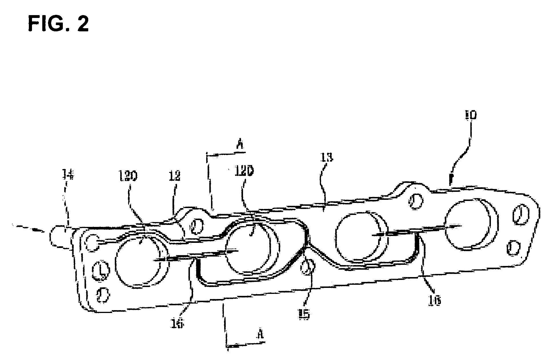
[0007] Another objection of the present invention is to provide an EGR distributor in which the lengths of delivery lines for recirculated exhaust gas to each cylinder are substantially equal with each other, whereby variations in the amount of exhaust gas recirculated to each intake passage can be reduced and the overall efficiency of the EGR system improved.

Problems solved by technology

However, such EGR systems are disadvantageous in that the cooler results in an increase in the number of components and mechanical complexity of the system.
Furthermore, the EGR systems are disadvantageous because the systems require sophisticated work in connecting the coolant pipe to the EGR distributor.
Because the recirculated exhaust gas is supplied to the cylinders through a pipe, to which each cylinder is connected in series, the amount of exhaust gas recirculated to each cylinder is not uniformly distributed.

Method used


Image

  • Exhaust gas recirculation (EGR) system
  • Exhaust gas recirculation (EGR) system
  • Exhaust gas recirculation (EGR) system

Examples


Embodiment Construction

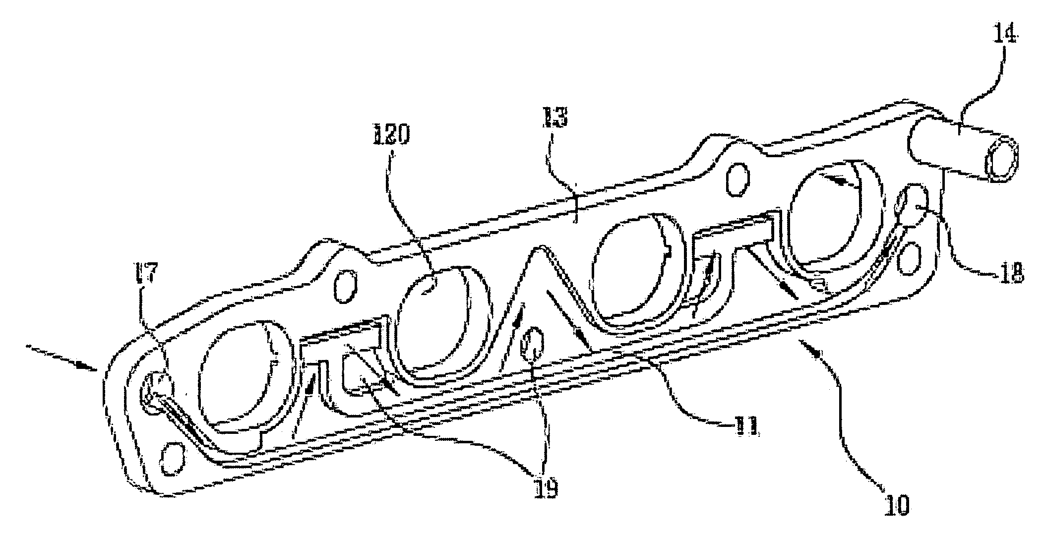
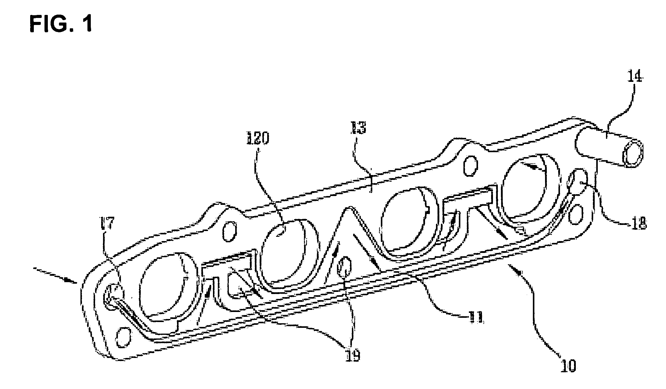
[0017] According to FIG. 1, a cooling means is integrated with an EGR distributor 10. An EGR distributor 10 serves to distribute exhaust gas recirculated from an exhaust line to intake passages. The EGR distributor 10 includes an EGR plate 13, which may be in the form of a single plate type or a multi-plate type. Formed in the EGR plate 13 is a plurality of intake passages 120 corresponding to each runner of the intake manifold 110 (FIG. 5). For example, a four-cylinder engine is provided with four intake passages.

[0018] The front face of the EGR plate 13 is furnished with a coolant passage 11 in the form of a groove. The coolant passage 11 is in coolant communication with a coolant inlet 17 and a coolant outlet 18, wherein the coolant inlet 17 and the coolant outlet 18 are connected to a coolant passage of a cylinder head. With such an arrangement, coolant is introduced into the coolant passage 11 of the EGR plate from the cylinder head through the coolant inlet 17 and is discharg...


PUM


Abstract

An EGR system has an EGR distributor in the form of a single plate integrally equipped with an exhaust gas passage and a coolant passage for recirculated exhaust gas therewith. The lengths of each exhaust gas passages for the recirculated exhaust gas to reach each cylinder are equal to each other, whereby the amount of the exhaust gas recirculated to each intake passage is same and the overall efficiency of the EGR system is improved. The EGR distributor is preferably manufactured in the form of a single component by AL die casting method.

Description

CROSS-REFERENCE TO RELATED APPLICATION(S) [0001] This application claims priority to Korean Application No. 10-2004-0027132, filed on Apr. 20, 2004, the disclosure of which is incorporated fully herein by reference. TECHNICAL FIELD OF THE INVENTION [0002] Generally, the present invention relates to a distributor of recirculated exhaust gas to cylinders of a combustion engine employing an Exhaust Gas Recirculation EGR system. More particularly, the distributor is in the form of a single plate integrally equipped with a delivering means and a cooling means for recirculated exhaust gas thereon. BACKGROUND OF THE INVENTION [0003] Typically, in order to control emissions of nitrogen oxides (NOx), recent automobiles are furnished with an EGR. The typical EGR system recirculates a part of the exhaust gas into an intake line so that the combustion temperature at a cylinder of an engine is lowered. For example, Japanese patent publication No. 2003-97369 discloses an intake device comprising ...

Claims


Application Information

Patent Timeline
Patent Type & Authority Applications(United States)
IPC IPC(8): F02M25/07F02M35/10
CPCF02M25/072F02M25/0735F02M25/0751F02M35/10085Y02T10/121F02M35/10268F02M35/10327F02M35/1036F02M35/10222F02M26/17F02M26/30F02M26/44E04C2/284
Inventor YI, JEA WOONG
Owner HYUNDAI MOTOR CO LTD
Learn More