Elevator traction sheave

A technology of elevator traction and rims, which is applied to elevators, transportation and packaging in buildings, can solve the problems of inconvenience, affecting the stability of traction wheels, increasing costs, etc., and achieve the effect of extending the stability

Inactive Publication Date: 2013-01-02
WUJIANG HUAMAO MACHINERY MFG
View PDF6 Cites 6 Cited by
  • Summary
  • Abstract
  • Description
  • Claims
  • Application Information

AI Technical Summary

Problems solved by technology

At present, the rope grooves are directly set on the outer wall of the rim or the outer wall of the secondary rim extending from one end of the rim. Once a single rope groove is damaged, or it is barely used, the stability of the traction sheave is affected, or the entire traction sheave needs to be replaced. Bring inconvenience to normal work and increase costs

Method used


Image

  • Elevator traction sheave
  • Elevator traction sheave

Examples


Embodiment Construction

[0017] The present invention will now be described in further detail with reference to the drawings and embodiments. These drawings are simplified schematic diagrams, which only illustrate the basic structure of the present invention in a schematic manner, and therefore only show the constitutions related to the present invention.

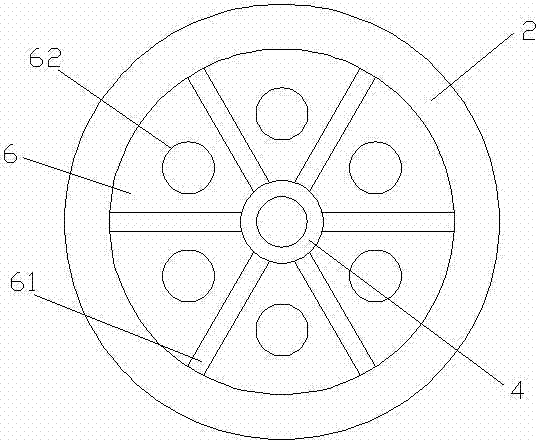
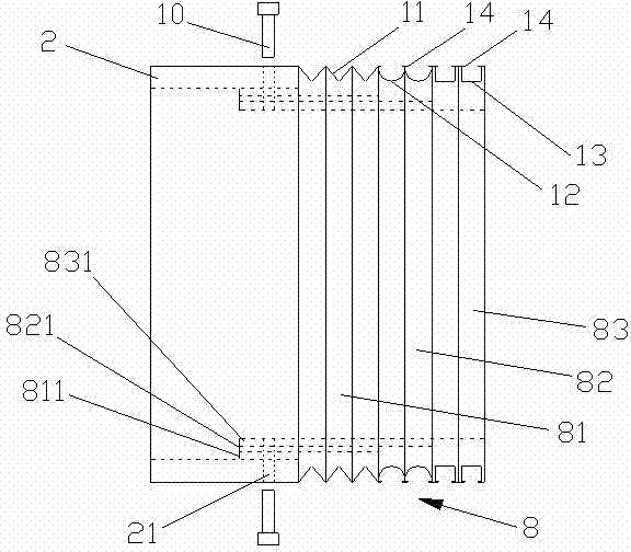
[0018] Such as Figure 1-2 As shown, an elevator traction sheave of the present invention includes an annular rim 2 and a wheel cylinder 4 arranged in the center of the rim 2 and coaxial with the rim 2, between the rim 2 and the wheel cylinder 4 It is connected by an annular connecting portion 6 perpendicular to the axial direction. One end of the rim 2 is provided with a secondary rim 8 that is separately connected to the rim 2, and the outer wall of the secondary rim 8 is provided with a radially recessed rope groove in the circumferential direction. The connecting portion 6 is provided with 6 radial reinforcement ribs 61 evenly distributed in the c...


PUM


Abstract

The invention relates to an elevator traction sheave. The elevator traction sheave comprises a circular ring shaped wheel rim and a wheel cylinder arranged at the center of the wheel rim and coaxial with the wheel rim, wherein the wheel rim is connected with the wheel cylinder through an annular connecting portion perpendicular to the axial direction. One end of the wheel rim is provided with an auxiliary wheel rim, and the periphery of an outer wall of the auxiliary wheel rim is provided with radial sunken rope grooves. The elevator traction sheave is characterized in that the auxiliary wheel rim and the wheel rim are split and connected through threads. The elevator traction sheave is provided with the auxiliary wheel rim and the wheel rim which are combined in a split mode, facilitates replacement the auxiliary wheel rim with the rope grooves or a damaged auxiliary wheel rim suitable for different conditions, and prolongs the overall service life of the traction sheave while ensuring the connecting stability of the wheel rim and the auxiliary wheel rim. The number of the rope grooves can be adjusted, and the auxiliary wheel rim can be set to be combined type, so that the flexible control of shapes of the rope grooves is facilitated, and the advantages of different rope grooves are complemented. Limiting protrusions are further arranged at the opening positions of the rope grooves, thereby facilitating the stability of traction ropes in the rope grooves.

Description

Technical field [0001] The invention relates to a traction sheave in elevator power equipment, in particular to a traction sheave with a rope groove. Background technique [0002] The power equipment of the elevator is mainly the traction machine, which specifically includes the motor, brake, coupling, reduction box, traction sheave and frame. Among them, the traction sheave is also called a traction sheave or a sheave, which is a device for elevators to transmit traction power. It uses the friction force between the traction wire rope and the rope groove on the traction rim to transmit power. The worm wheel installed in the reducer Shaft. At present, the rope groove is directly arranged on the outer wall of the rim or the outer wall of the secondary rim extending from one end of the rim. Once the individual rope grooves are damaged, or the reluctance of use affects the stability of the traction sheave, or the entire traction sheave needs to be replaced, Bring inconvenience to ...

Claims


Application Information

Patent Timeline
Patent Type & Authority Applications(China)
IPC IPC(8): B66B11/08
Inventor 陈林华
Owner WUJIANG HUAMAO MACHINERY MFG
Why Eureka
Try Eureka