
Supercharged engine intake manifold for integrated intercooler

A supercharged engine and intake manifold technology, which is applied in the direction of machines/engines, engine components, combustion engines, etc., can solve the problem of insufficient utilization of the heat exchange area of ​​the intercooler, unreasonable design of the intake manifold diversion, and shortened The service life of the intake manifold and other issues can be improved to improve the cooling effect, benefit the stability and improve the heat exchange efficiency

Active Publication Date: 2013-01-02
GREAT WALL MOTOR CO LTD
View PDF6 Cites 25 Cited by
  • Summary
  • Abstract
  • Description
  • Claims
  • Application Information

AI Technical Summary

Problems solved by technology

[0003] At present, most turbocharged engines in China connect the supercharged fresh air to the intercooler of the whole vehicle through pipelines. Due to the long connection pipeline and complicated structure, the pressure loss of the gas after cooling is large, and it is easy to be heated again, which makes the Reduced charging efficiency of the engine, which in turn affects engine performance
Although some supercharged engines adopt the technology of intake manifold integrated intercooler, the design of the intake manifold has the following defects. First, the intake manifold diversion design is unreasonable, and the gas cannot be effectively divided and then passed through the intercooler The second is that the heat exchange area of ​​the intercooler is not fully utilized, resulting in a partial dead zone in the cooling pipeline; the third is that the high-temperature gas impacts the intake manifold header for a long time after supercharging, which shortens the service life of the intake manifold; the fourth is The cooling water flow of most intercoolers is in the same direction as the intake air, resulting in low gas cooling efficiency

Method used


Image

  • Supercharged engine intake manifold for integrated intercooler
  • Supercharged engine intake manifold for integrated intercooler
  • Supercharged engine intake manifold for integrated intercooler

Examples


Embodiment Construction

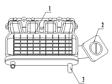
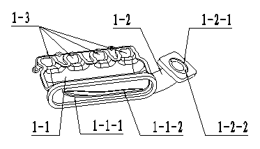
[0021] See Figure 1, figure 2 , the present invention includes an intake manifold body 1, a metal bush 2 and an intercooler 3, the intake manifold body 1 is provided with an intake manifold 1-2, a plenum chamber 1-1 and an intake branch pipe 1- 3. The rear end of the plenum chamber 1-1 is connected to the intake branch pipe 1-3, the bottom of the plenum chamber 1-1 communicates with the intake manifold 1-2, and the metal bushing 2 is embedded in the intake manifold 1 -2, the intercooler 3 is integrated in the plenum chamber 1-1.

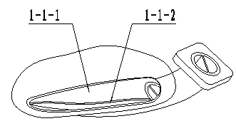
[0022] see figure 2 , image 3 , Figure 4 , the bottom surface of the plenum chamber 1-1 of the present invention is provided with an air intake guide groove 1-1-1 connected to the intake manifold 1-2, and a vertical deflector is arranged in the air intake guide groove 1-1-1 1-1-2, the top surface of the vertical deflector 1-1-2 is an arc-shaped space surface, and the number of arcs matching the number of engine cylinders is provided at the re...


PUM


Abstract

The invention discloses a supercharged engine intake manifold for an integrated intercooler. The supercharged engine intake manifold is used for decreasing the intake temperature of a turbo supercharged engine and improving the intake efficiency of the engine, and comprises an intake manifold body, a metal bushing and an intercooler, wherein the intake manifold body is provided with an intake manifold, a pressure stabilizing chamber and intake branch pipes; the rear end of the pressure stabilizing chamber is connected with the intake branch pipes and the bottom of the pressure stabilizing chamber is communicated with the intake manifold; the metal bushing is embedded in the intake manifold; and the intercooler is integrated in the pressure stabilizing chamber. According to the supercharged engine intake manifold for the integrated intercooler, the intercooler is integrated in the pressure stabilizing chamber of the intake manifold, the pressure loss of cooled gas caused by a long connecting pipeline is avoided, the temperature of supercharged air is effectively reduced, and the charging efficiency of the engine is improved, so that the power performance and economic performance of the engine are improved.

Description

technical field [0001] The invention relates to an intake manifold of a turbocharged engine, in particular to an engine intake manifold integrated with an intercooler, and belongs to the technical field of engines. Background technique [0002] Since the air intake mode of the turbocharged engine has changed from natural suction to forced pressurized air intake, the gas temperature will rise significantly. Excessively high intake air temperature will cause the gas to expand, resulting in a decrease in intake efficiency, which directly affects the performance of the engine. Combustion conditions, so the turbocharged engine needs to reduce the intake air temperature through the intercooler. [0003] At present, most turbocharged engines in China connect the supercharged fresh air to the intercooler of the whole vehicle through pipelines. Due to the long connection pipeline and complicated structure, the pressure loss of the gas after cooling is large, and it is easy to be heat...

Claims


Application Information

Patent Timeline
IPC IPC(8): F02M35/104F02B29/04
CPCY02T10/146Y02T10/12
Inventor 孙青山刘胜强王航赵玉振辛宇
Owner GREAT WALL MOTOR CO LTD
Features
  • Generate Ideas
  • Intellectual Property
  • Life Sciences
  • Materials
  • Tech Scout
  • Unparalleled Data Quality
  • Higher Quality Content
  • 60% Fewer Hallucinations
Learn More