
Reflector and anti-explosion lamp

A reflector and explosion-proof lamp technology, applied in the field of lighting, can solve the problems of temperature rise of transparent parts, poor heat dissipation of explosion-proof lamps, etc., and achieve the effects of reducing temperature rise, increasing effective output light intensity, and reducing temperature rise

Inactive Publication Date: 2013-01-02
OCEANS KING LIGHTING SCI&TECH CO LTD +1
View PDF3 Cites 0 Cited by
  • Summary
  • Abstract
  • Description
  • Claims
  • Application Information

AI Technical Summary

Problems solved by technology

[0003] The purpose of the present invention is to provide a reflector, aiming to solve the problem of excessive temperature rise of the transparent part of the explosion-proof lamp due to poor heat dissipation

Method used


Image

  • Reflector and anti-explosion lamp
  • Reflector and anti-explosion lamp
  • Reflector and anti-explosion lamp

Examples


Embodiment 1

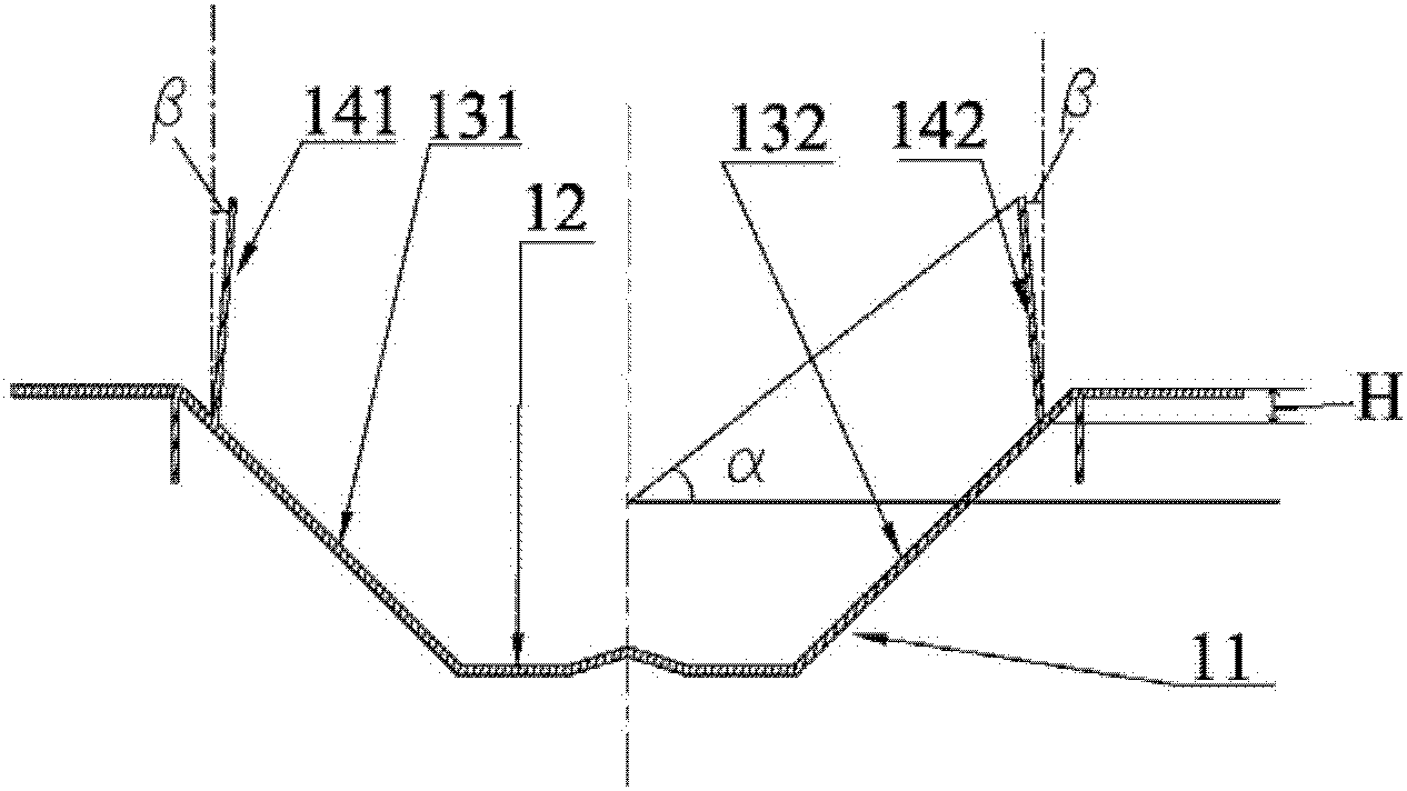
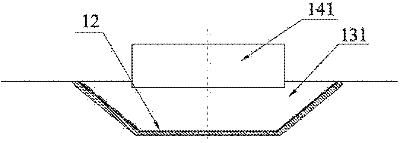
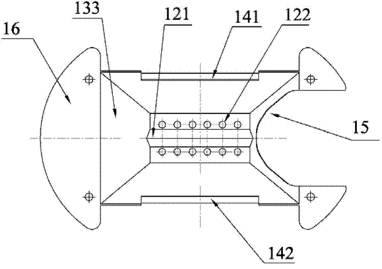
[0015] combined with Figures 1 to 3 , the reflector provided in this embodiment is mainly used in explosion-proof lamps. The light-emitting center of the light source of the explosion-proof lamp is located in the reflector, and the transparent part is installed at the light outlet of the reflector. The reflector has both light distribution and reduction transparent parts. effect of temperature rise. The reflector includes a groove-shaped body 11, the interior of the body 11 is provided with a reflective surface, the reflective surface at least includes a bottom surface 12 and two oppositely arranged side surfaces, namely a first side surface 131 and a second side surface 132, here It should be understood that the bottom surface and the two side surfaces are both elongated structures; a light shielding plate, namely a first light shielding plate 141 and a second light shielding plate 142, respectively, extends outward from the upper part of the two side surfaces. These two lig...

Embodiment 2

[0028] combined with Figures 4 to 6 , this embodiment provides an explosion-proof lamp, which includes the above-mentioned reflector. Specifically, the explosion-proof lamp includes a lamp housing 41 and a lamp cover 42, and a reflector 43 is provided inside the lamp housing 41, and the reflector 43 is provided inside the lamp housing 41. A light source 44 is provided inside the reflector 43 , a transparent member 45 is installed at the light outlet of the reflector 43 , the lamp housing 41 is butted with the lamp cover 42 , and the transparent member 45 and the reflector 43 are pressed and fixed.

[0029] Specifically, the strip light source passes through the side end of the reflector 43 and is located in the middle of the reflector, and the light emitted by the light source is reflected by the reflector and then exits through the transparent member 45 . The structure of the transparent member 45 is adapted to the structure of the reflector 43. Since the reflector 43 is a g...


PUM


Abstract

The invention is applied to the field of illumination and provides a reflector and an anti-explosion lamp. The reflector comprises a groove-shaped body in which a reflecting face is arranged; the reflector at least comprises a bottom face and two oppositely-mounted sides, each of the upper parts of the two sides is provided with a light shielding plate in an outwards-extending mode, and the upper parts of the two light shielding plates incline inwards relative to the central lines of the two sides. As the two sides of the reflector are provided with the light shielding plates for shielding light irradiating towards the direction below a transparent piece, the temperature rise of the transparent piece is reduced; the upper parts of the two light shielding plates incline inwards and can reflect light irradiating to the light shielding plates to the bottom part of the reflector, then the light is reflected with a smaller emergence angle by the bottom face, the part of reflected light is projected via the front end of the transparent piece, and therefore, the effective emergence light intensity is increased and the light distribution efficiency of the lamp is improved; and the temperature rise of the transparent piece of the anti-explosion lamp adopting the reflector can be greatly reduced, the requirements of explosion prevention certification standards are met, and potential safety troubles are eliminated.

Description

technical field [0001] The invention belongs to the field of lighting, and in particular relates to a reflector and an explosion-proof lamp. Background technique [0002] Explosion-proof lamps are mainly used for lighting in indoor and outdoor explosion-proof places such as petrochemical plant platforms and workshops, oil drilling platforms and offshore oil drilling platforms, on-site offices with explosion-proof requirements, on-site control rooms, construction sites and other places containing flammable and explosive gases. If the temperature of the lamp is too high, the lamp will become a heat source, and a large amount of flammable gases (such as gas and fuel) contained in the air may explode the lamp, which will directly endanger the safety of national property and citizens. The explosion-proof certification standards stipulated by the state have clear requirements for the temperature of explosion-proof lamps. Therefore, heat dissipation performance is particularly imp...

Claims


Application Information

Patent Timeline
Patent Type & Authority Applications(China)
IPC IPC(8): F21V1/24F21V7/00
Inventor 周明杰林华军杜勇强
Owner OCEANS KING LIGHTING SCI&TECH CO LTD
Learn More