Projection device and circuit board module

A projection device and circuit board technology, which is applied to projection devices, electrical components, electrical equipment shells/cabinets/drawers, etc., can solve the problems of polluting electronic components and optical components, light leakage, and poor projection quality of projection devices, etc., and achieve good heat dissipation Efficiency, the effect of avoiding light leakage

Inactive Publication Date: 2013-01-02
CORETRONIC
View PDF8 Cites 3 Cited by
  • Summary
  • Abstract
  • Description
  • Claims
  • Application Information

AI Technical Summary

Problems solved by technology

However, external dust or other foreign matter will enter the interior of the projection device through the opening to contaminate its electronic components and optical components, and the light emitted by the light source inside the projection device will also leak through the above-mentioned opening to cause light leakage. This affects the normal operation and projection quality of the projection device
[0004] U.S. Patent No. 20060265732 discloses an adapter and a c

Method used


Image

  • Projection device and circuit board module
  • Projection device and circuit board module
  • Projection device and circuit board module

Examples


Example Embodiment

[0032] The foregoing and other technical contents, features, and effects of the present invention will be clearly presented in the detailed description of multiple embodiments below with reference to the drawings. The directional terms mentioned in the following embodiments, such as "up", "down", "front", "rear", "left", "right", etc., are only directions for referring to the attached drawings. Therefore, the directional terms used are used to illustrate rather than to limit the present invention.

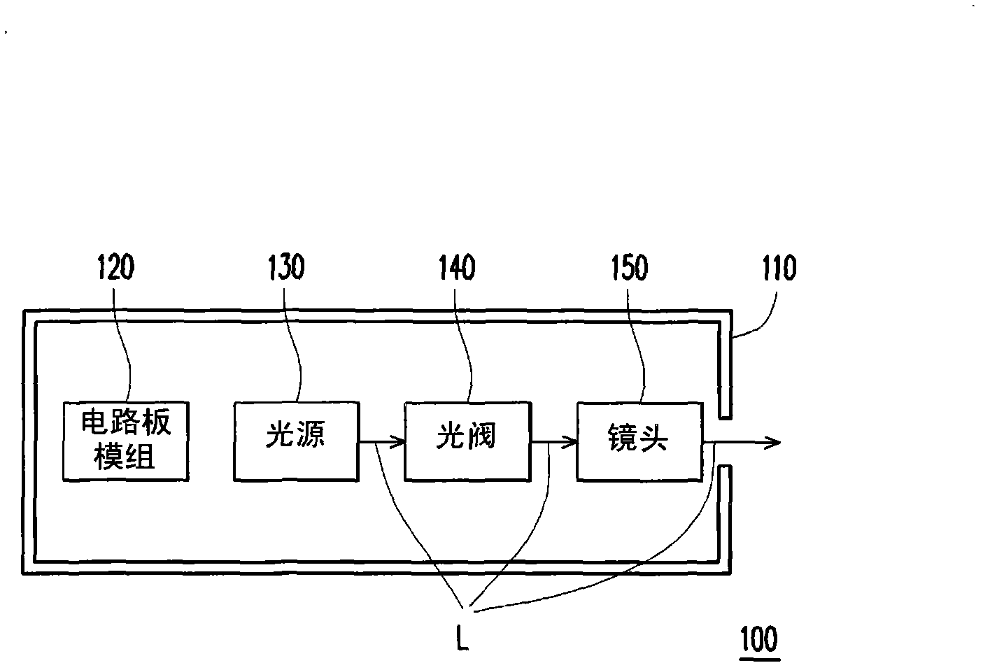
[0033] figure 1 It is a schematic diagram of a projection device according to an embodiment of the invention. Please refer to figure 1 The projection device 100 of this embodiment includes a housing 110, a circuit board module 120, a light source 130, a light valve 140, and a lens 150. The circuit board module 120, the light source 130, the light valve 140 and the lens 150 are arranged in the housing 110. The light beam L emitted by the light source 130 passes through the light valv...


PUM


Abstract

Provided are a projection device and a circuit board module. The projection device comprises a casing, the circuit board module, a light source, a light valve and a camera lens, and the casing is provided with at least one opening hole. The circuit board module comprises a circuit board, a plate element, an elastic structure and at least one connector. The circuit board and the plate element are arranged in the casing. The elastic structure is clamped between the circuit board and the plate element. The circuit board, the plate element and the elastic structure separate the inside of the casing into a first space and a second space. The first space is separated from the second space through sealing of the elastic structure, and the first space is communicated with the outside through the opening hole. The connector is allocated on the circuit board to be located in the first space, and the connector is exposed out by the opening hole. The light source, the light valve and the lens are allocated in the second space. Light beams sent from the light source reach the lens through the light valve.

Description

【Technical field】 [0001] The present invention relates to an optical device and its circuit board module, and in particular to a projection device and its circuit board module. 【Background technique】 [0002] A projection device is a display device for producing large-scale images. The imaging principle of the projection device is to convert the illumination beam generated by the light source into an image beam through a light valve, and then project the image beam onto a screen or a wall through a lens to form an image. With the advancement of projection technology and the reduction of manufacturing costs, the use of projection devices has gradually expanded from commercial use to home use. [0003] Generally speaking, a connector is provided on the circuit board inside the projector, and the connector is connected to an external power source or receives signals from other peripheral devices. In order for the connector to be connected to an external power line or data tra...

Claims


Application Information

Patent Timeline
IPC IPC(8): G03B21/14H05K5/00
Inventor 黄建昌张汎杰
Owner CORETRONIC
Why Eureka
Try Eureka