Proximity exposure device

An exposure device and proximity technology, which are applied in the direction of photolithography process exposure device, microlithography exposure equipment, etc., can solve the problems of substrate temperature increase, exposure accuracy influence, large temperature difference, etc., to achieve high-precision exposure, inhibit exposure The effect of the effect of precision

Active Publication Date: 2013-01-02
V TECH CO LTD
View PDF9 Cites 8 Cited by
  • Summary
  • Abstract
  • Description
  • Claims
  • Application Information

AI Technical Summary

Problems solved by technology

However, in the case of using a linear motor, the heat generated from the linear motor will cause the temperature of the table to rise, and the temperature of the substrate held by the table will also rise accordingly
Linear motors have problems such as a large temperature difference between the running period and the shutdown period, and the heat from the workbench causes the substrate to expand or shrink, or local temperature unevenness, which greatly affects the accuracy of exposure, etc.

Method used


Image

  • Proximity exposure device
  • Proximity exposure device
  • Proximity exposure device

Examples


no. 1 approach

[0112] Hereinafter, the first embodiment of the proximity exposure apparatus of the present invention will be described in detail based on the drawings.

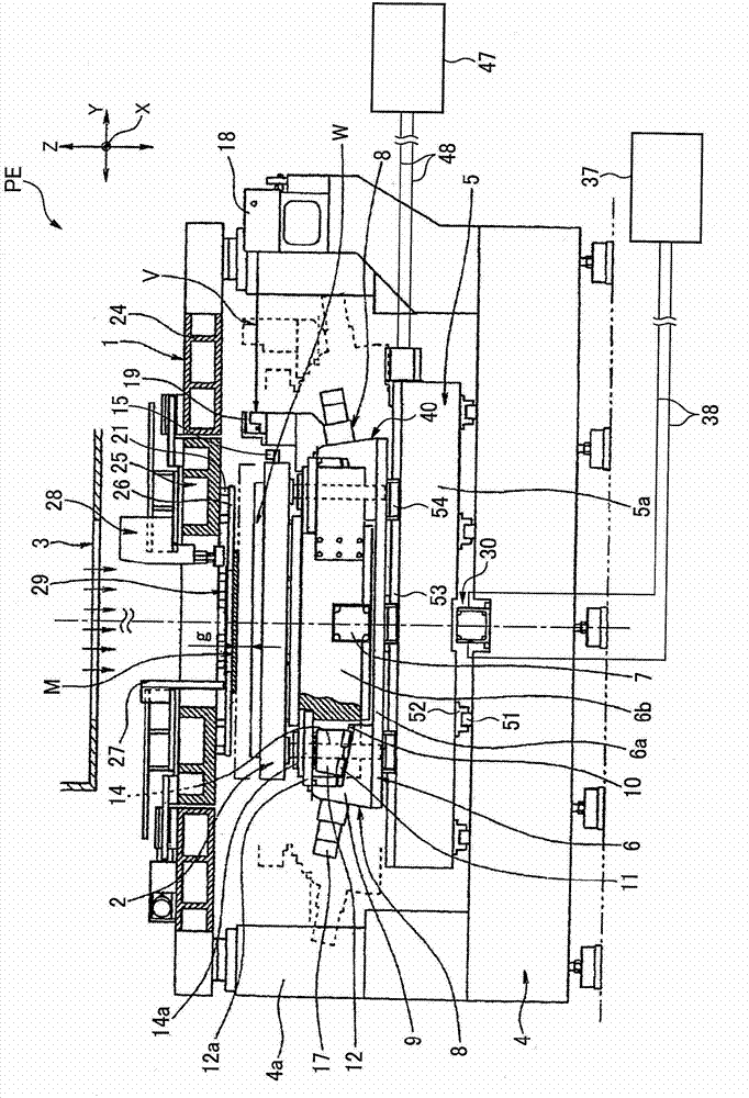
[0113] figure 1 It is a partial cross-sectional front view for explaining the step-by-step exposure apparatus according to the first embodiment of the present invention. Such as figure 1 As shown, the step-and-proximity exposure apparatus PE uses a mask M smaller than the substrate W as the object to be exposed, and holds the mask M with the mask loading table 1, and holds the substrate W with the workbench 2, so that the mask M and The pattern exposure of the mask M is transferred onto the substrate W by irradiating pattern exposure light from the irradiation device 3 to the mask M with the substrates W approaching and facing each other with a predetermined exposure gap. In addition, the stage 2 is moved in two axial steps of the X-axis direction and the Y-axis direction relative to the mask M, and the exposure transfer i...

no. 2 approach

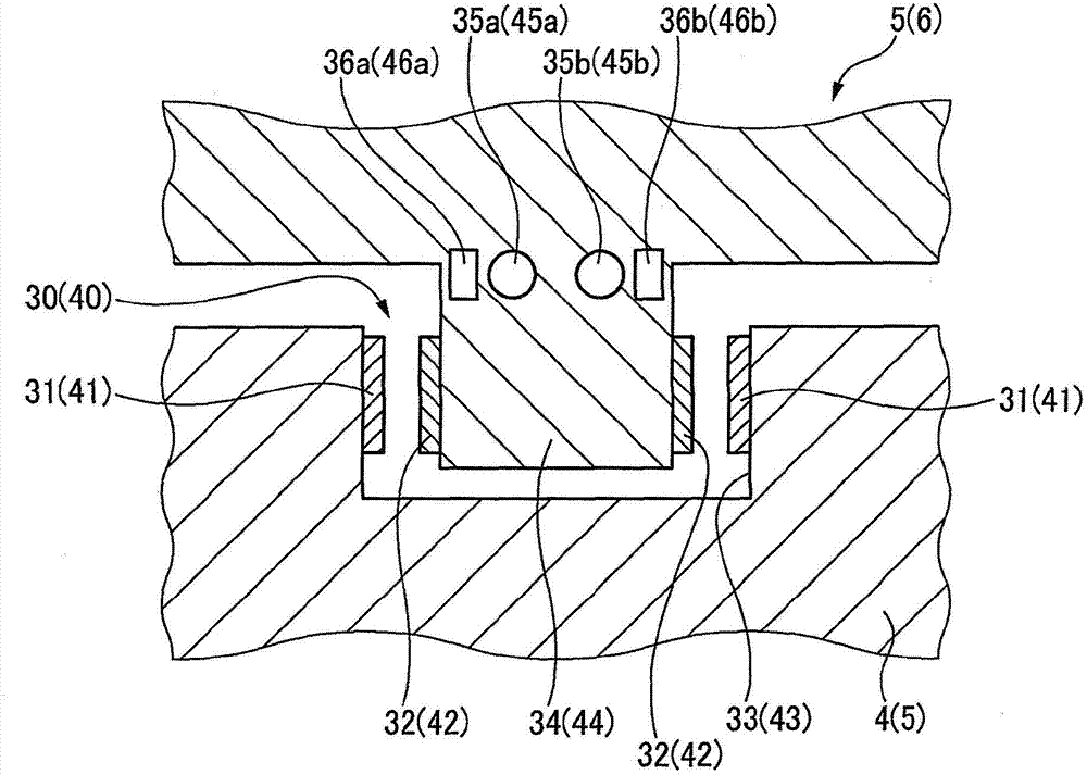
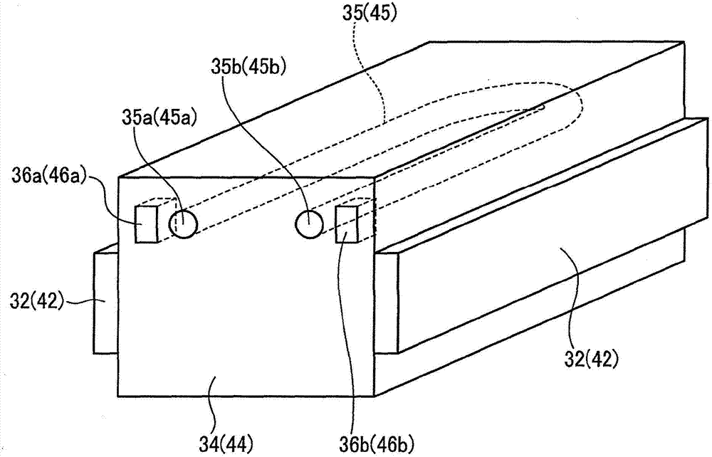
[0155] Below, refer to Image 6 with Figure 7 Next, a proximity exposure apparatus according to a second embodiment will be described. In the first embodiment, the configuration in which the refrigerant circulation passage is arranged along the rotor was described, but this embodiment includes a configuration in which the refrigerant circulation passage is arranged along the stator.

[0156] That is, if Image 6 with Figure 7 As shown, the proximity exposure apparatus according to the second embodiment of the present invention, in addition to having the first and second rotor-side refrigerant circulation passages 35 provided on the X-axis conveying table 5a and the Y-axis conveying table 6a in the above-mentioned embodiment , 45, there are also substantially U-shaped first and second stator side refrigerant circulation passages arranged on the base 4 and the X-axis loading platform conveying mechanism 5 along the first and second stators 31, 41 respectively 70, 80. Spec...


PUM


Abstract

The invention relates to a proximity exposure (PE) device, comprising a workpiece driving part formed by a first linear motor (30) having a first stator (31) and a first rotor (32) opposite to the first stator (31) and a second linear motor (40) having a second stator (41) and a second rotor (42) opposite to the second stator (41); refrigerant circulation paths (35, 45) configured along the rotors (32, 42); refrigerant supply devices (37, 47) for circularly supplying refrigerants to the refrigerant circulation paths (35, 45); and temperature sensors (36, 46) which are configured in the vicinity of inlets (35a, 45a) and outlets (35b, 45b) of the refrigerant circulation paths (35, 45) to detect the refrigerant inlet / outlet temperature. Temperature is managed based on detection values of the temperature sensors (36, 46), thereby making fixed the amount of heat that is transferred from the linear motors (30, 40) to a substrate (W).

Description

technical field [0001] The present invention relates to a proximity exposure device, more specifically, to a proximity exposure device suitable for exposing and transferring a mask pattern on a substrate such as a large flat panel display such as a liquid crystal display or a plasma display. Background technique [0002] Proximity exposure is to keep the light-transmitting substrate (the object to be exposed) coated with a photosensitive agent on the work stage of the exposure device, and at the same time make the substrate and the mask holding frame held on the mask loading table The mask is close to each other, and the gap between the two is, for example, tens of microns to hundreds of microns. Using an irradiation device, the mask is irradiated with exposure light from the side of the mask opposite to the substrate, thereby drawing A technique in which exposure patterns on a mask are transferred to a substrate. [0003] On the other hand, in proximity exposure, there is ...

Claims


Application Information

Patent Timeline
Patent Type & Authority Applications(China)
IPC IPC(8): G03F7/20
Inventor 前田武文森本贺津美
Owner V TECH CO LTD
Why Eureka
Try Eureka