Exposure device and exposure method

A technology of exposure device and loading platform, which is applied in the direction of photolithography exposure device and microlithography exposure equipment, etc., which can solve the problems of resolution reduction, blurred image, and inability to expose fine patterns.

Inactive Publication Date: 2013-01-02
NSK TECH
View PDF14 Cites 13 Cited by
  • Summary
  • Abstract
  • Description
  • Claims
  • Application Information

AI Technical Summary

Problems solved by technology

However, in such an exposure apparatus, since the mask pattern formed on the mask is transferred to the substrate as it is by the exposure light that passes through the mask vertically, t

Method used


Image

  • Exposure device and exposure method
  • Exposure device and exposure method
  • Exposure device and exposure method

Examples


no. 1 approach

[0160] Hereinafter, an embodiment of the exposure apparatus according to the first embodiment of the present invention will be described in detail based on the drawings.

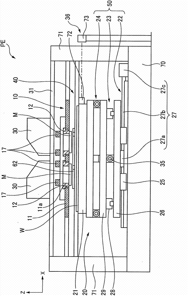
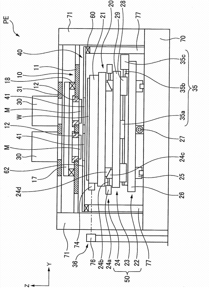
[0161] figure 1 is a front view of the exposure device of the present invention, figure 2 is its side view. Such as figure 1 and figure 2 As shown, the exposure apparatus PE of this embodiment has: a mask mounting table 10 holding a mask M; a substrate mounting table 20 on which a glass substrate (object to be exposed) W is mounted; Axis, Z-axis direction, and adjust the inclination of the substrate loading table 20 of the substrate loading table moving mechanism 50 and the microlens array 41, and arrange the microlens loading between the substrate loading table 20 and the mask loading table 10 stage 40 ; and illumination optical system 30 for irradiating pattern exposure light to substrate W via mask M and microlens array 41 .

[0162] It should be noted that the glass substrate W (hereinafter, simpl...

no. 2 approach

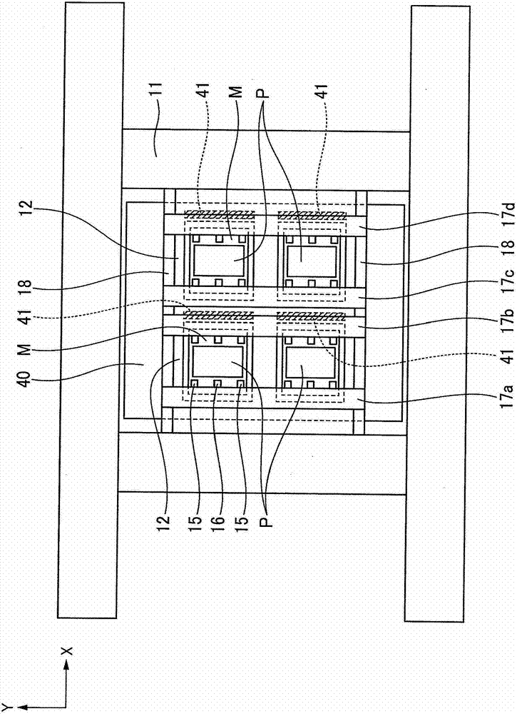
[0214] Figure 10 (a) and (b) are the top view and cross-sectional view of the microlens mounting plate provided with the nozzle which is the exposure apparatus of 2nd Embodiment. Such as Figure 10 As shown, on both sides of the microlens mounting plate 62 extending in the Y direction that is not held by the microlens mounting plate 62 , a plurality of nozzles 45 are formed on the upper and lower surfaces thereof. The plurality of nozzles 45 communicate with air supply holes 46 formed in the microlens mounting plate 62 . The plurality of nozzles 45 spray air supplied from an air supply device (not shown) in at least one of upward and downward directions through the air supply holes 46 .

[0215] As a result, as shown by the dotted line in the figure, deflection of the microlens mounting plate 62 deflected by its own weight can be corrected, thereby preventing uneven exposure due to deflection of the microlens mounting plate 62 . It should be noted that it is also possible ...

no. 3 approach

[0223] Below, refer to Figure 12 to Figure 14 An exposure apparatus according to a third embodiment of the present invention will be described. In addition, the same or equivalent parts as those of the first embodiment are assigned the same symbols, and descriptions thereof are omitted or simplified.

[0224] Such as Figure 12 and Figure 13 As shown, in this embodiment, the mask stage 10 is provided with a cover glass 90 made of glass or resin on the upper part of the mask holding frame 12, and is formed by the mask M, the mask holding frame 12, and the cover glass 90. In the highly airtight space, the pressure in the highly airtight space is adjusted by a pressure control mechanism not shown to compensate for the deformation of the mask.

[0225] In addition, if Figure 14 As shown, on the surface facing the mask holding frame 12 around the cover glass 90, a film 91 made of a resin such as polyacetal, polyamide, or ABS resin is pasted as a covering member. Thus, when ...


PUM


Abstract

The invention relates to an exposure device and an exposure method, capable of exposing and transferring a microfine exposure pattern on a substrate by using a micro lens array with high resolution at relatively short production takt interval. The exposure device of the invention comprises a mask loading platform (10); a substrate loading platform (20); an illuminating optical system (3) for irradiating lights for pattern exposure; a micro lens carrying plate (62), which has a micro lens array (41) that is formed by directional configuration of multiple micro lenses (42) on a plane and is extended in a linear manner along the Y direction, and is configured between a mask (M) and the substrate (W); and a micro lens driving mechanism (60) for enabling the micro lens carrying plate (62) to move along the X direction. When the micro lens carrying plate (62) moves along the X direction, lights for pattern exposure are irradiated to expose and transfer the mask pattern on the substrate (W) with the help of the micro lens (42).

Description

technical field [0001] The present invention relates to an exposure device and an exposure method, and more specifically, to an exposure device and an exposure method capable of transferring a fine exposure pattern onto the entire surface of a substrate with high-resolution exposure. Background technique [0002] A conventional exposure apparatus brings a mask and a substrate close to each other with a small gap therebetween, irradiates pattern exposure light from an illumination optical system through the mask, and transfers the pattern exposure formed on the mask to the substrate. However, in such an exposure apparatus, since the mask pattern formed on the mask is transferred to the substrate as it is by the exposure light passing through the mask vertically, the substrate may be damaged due to light refraction. The image of the pattern on the surface is blurred and the resolution is reduced, so that it is impossible to expose the fine pattern. [0003] In order to deal w...

Claims


Application Information

Patent Timeline
IPC IPC(8): G03F7/20
Inventor 佐治伸仁小林健一原田种真桐生恭孝小柳秀昭今井克喜长谷川一也
Owner NSK TECH
Why Eureka
Try Eureka