Cassegrain type metamaterial antenna

A metamaterial and antenna technology, applied in the field of communication, can solve the problems of high cost and difficult processing of the Cassegrain antenna, and achieve the effects of easy manufacturing and processing and low cost

Active Publication Date: 2013-01-02
KUANG CHI INST OF ADVANCED TECH
View PDF6 Cites 9 Cited by
  • Summary
  • Abstract
  • Description
  • Claims
  • Application Information

AI Technical Summary

Problems solved by technology

[0004] The technical problem to be solved by the present invention is to provide a Cassegrain-type metamaterial antenna with simple processing and low manufacturing cost for the existing Cassegrain antennas that are difficult to process and high in cost

Method used


Image

  • Cassegrain type metamaterial antenna
  • Cassegrain type metamaterial antenna
  • Cassegrain type metamaterial antenna

Examples


Embodiment Construction

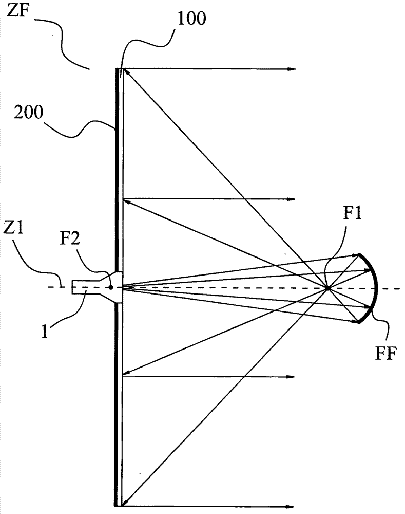
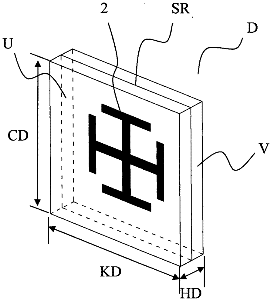
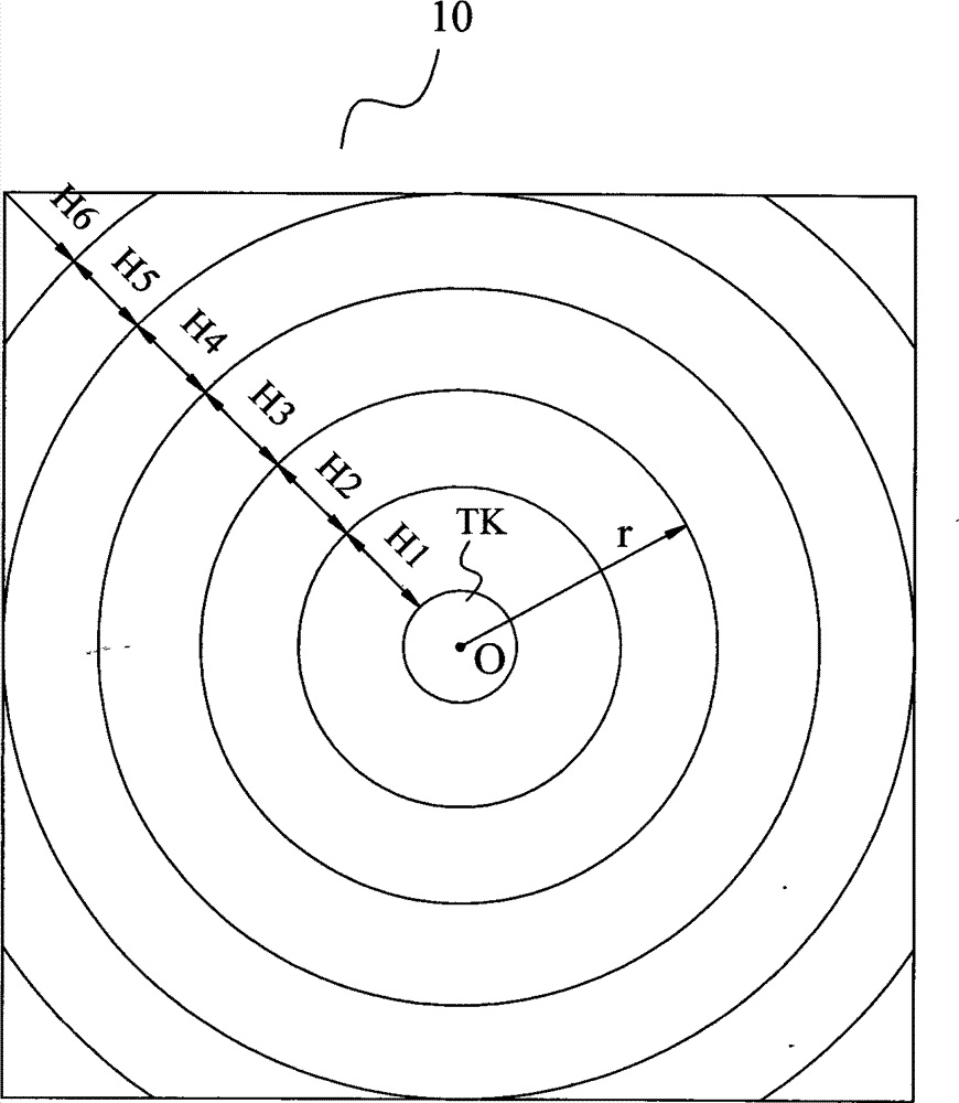
[0035] Such as Figures 1 to 4 As shown, the Cassegrain-type metamaterial antenna according to the present invention includes a metamaterial main reflector ZF with a central through hole TK, a feed source 1 arranged in the central through hole TK, and a sub-reflector arranged in front of the feed source 1 FF, the electromagnetic waves radiated by the feed source 1 are emitted in the form of plane waves after being reflected by the sub-reflector FF and the metamaterial main reflector ZF in turn, and the metamaterial main reflector ZF includes a core layer 100 and is arranged on the back surface of the core layer 100 The reflective layer 200, the core layer 100 includes at least one core layer sheet 10, the core layer sheet 10 includes a substrate JC and a plurality of artificial microstructures 2 disposed on the substrate JC, the sub-reflector FF is one of the curved surfaces of the spheroid, and the phase center of the feed 1 coincides with the far focus F2 of the spheroid. T...


PUM


Abstract

The invention discloses a cassssegrain type metamaterial antenna. The antenna comprises a main metamaterial reflector with a central through-hole, a feed source which is arranged in a central through-hole and an auxiliary reflector which is arranged in front of the feed source, wherein electromagnetic waves radiated by the feed source are sequentially subjected to the reflection of the auxiliary reflector and the main metamaterial reflector and are ejected in a plane wave mode, the main metamaterial reflector comprises a core layer and a reflection layer which is arranged on rear surface of the core layer, the core layer comprises at least one core layer sheet layer, the core layer sheet layer comprises a base material and a plurality of artificial microstructures which are arranged on the base material, the auxiliary reflector is one of curved surfaces of a rotary ellipse surface, and a phase center of the feed source overlaps a far focus of the rotary ellipse surface. According to the cassssegrain type metamaterial antenna, a conventional paraboloid is replaced with the main metamaterial reflector in a sheet shape, and the antenna is easy to produce and process and low in cost.

Description

technical field [0001] The invention relates to the communication field, and more specifically, relates to a Cassegrain-type metamaterial antenna. Background technique [0002] The Cassegrain antenna consists of three parts, namely the main reflector, sub-reflector and radiation source. Wherein the main reflector is a rotating paraboloid, and the secondary reflecting surface is one of the rotating hyperboloids. Structurally, one focus of the hyperboloid coincides with the focus of the paraboloid, the focal axis of the hyperboloid coincides with the focal axis of the paraboloid, and the radiation source is located at the other focus of the hyperboloid. The electromagnetic wave emitted by the radiation source is reflected by the sub-reflector once, and the electromagnetic wave is reflected to the main reflector, and then the plane wave beam in the corresponding direction is obtained after being reflected by the main reflector, so as to realize directional emission. [0003] ...

Claims


Application Information

Patent Timeline
Patent Type & Authority Applications(China)
IPC IPC(8): H01Q19/18H01Q15/14
Inventor 刘若鹏季春霖岳玉涛杨青殷俊
Owner KUANG CHI INST OF ADVANCED TECH
Why Eureka
Try Eureka