Hinge wiring harness buckling structure

A clasp structure and wire harness clip technology, which is applied in the direction of electrical components, can solve the problems of affecting the strength of the hinge and the inconvenience of adjusting the installation position of the harness clasp, achieving the effect of good versatility and improving convenience

Active Publication Date: 2013-01-02
HANGZHOU BRANCH ZHEJIANG GEELY AUTOMOBILE RES INST +2
View PDF5 Cites 4 Cited by
  • Summary
  • Abstract
  • Description
  • Claims
  • Application Information

AI Technical Summary

Problems solved by technology

[0007] The invention provides a convenient hinge wire harness buckle structure that can be installed without opening holes on the hinge when adjusting the installation position on the hinge. The problem of affecting the strength of the hinge due to the hole and the inconvenience of adjusting the installation position of the wire harness buckle on the hinge

Method used


Image

  • Hinge wiring harness buckling structure
  • Hinge wiring harness buckling structure
  • Hinge wiring harness buckling structure

Examples


Embodiment 1

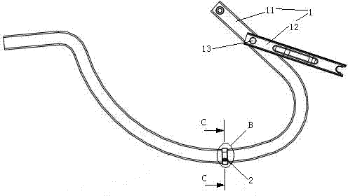
[0030] Embodiment one, see figure 1 , a hinged wire harness buckle structure, comprising a hinge 1 and a wire harness buckle 2 .

[0031] The hinge 1 includes a first connection part 11 and a second connection part 12 , and the first connection part 11 and the second connection part 12 are connected together by a hinge shaft 13 . The first connecting part 11 and the second connecting part 12 can rotate in a plane around the hinge axis 13 . The first connecting portion 11 is a rod-shaped structure. The cross sections of the first connecting portion 11 are congruent geometric figures. The entire first connecting portion 11 is a buckle installation section of the wire harness.

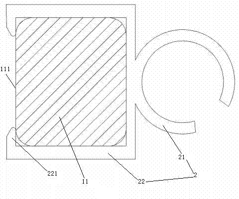
[0032] see figure 2, the wire harness buckle 2 includes a fixed wire harness portion 21 and a clip 22 . The fixed wire harness part 21 is a circular split ring structure with an elastic integral structure. The chuck 22 is a square split ring structure with elasticity. The fixed wire harness part 2...

Embodiment 2

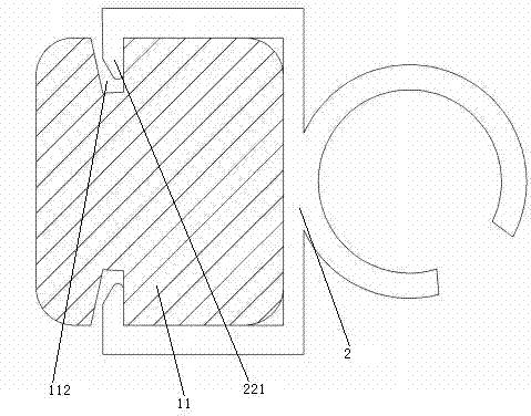
[0034] Embodiment two, see image 3 , the difference from the first embodiment is: the upper and lower surfaces of the first connecting part 11 are respectively provided with a groove 112 extending along the direction of the center line, and the hook head 221 is hooked on the groove 112 .

Embodiment 3

[0035] Embodiment three, see Figure 4 , the difference from the first embodiment is: the two ends of the first connecting portion 11 are provided with plate-shaped mounting heads 114 . The middle part of the first connecting portion 11 is provided with a wire harness buckle installation section 113 . The buckle installation section 113 of the wire harness is a rod-shaped structure. The wire harness buckle 2 is connected to the wire harness buckle installation section 113 .

[0036] see Figure 5 , the cross-section of the buckle installation section 113 of the wire harness is circular, and the clip 22 is a circular split ring structure with elasticity. A fixing surface 111 is cut out on the rear surface of the buckle installation section 113 of the wire harness. The fixing surface 111 extends along the direction of the centerline of the buckle installation section 113 of the wire harness. The generatrix of the fixing surface 111 is a straight line.


PUM


Abstract

The invention relates to wiring harness buckling and particularly relates to a hinge wiring harness buckling structure. The structure comprises a hinge and a wiring harness fastener, the hinge comprises a first connecting portion and a second connecting portion which can rotate relative to the first connecting portion, the wiring harness fastener comprises a wiring harness fixing portion, the first connecting portion is provided with a wiring harness buckling installation section, the wiring harness also comprises a chuck which can be opened or closed, and the chuck is clamped on the wiring harness installation section. According to the hinge wiring harness buckling structure, a hole is not required to be arranged on a hinge, the structure can be installed on the hinge and is convenient to adjust the installation position, and the problem that the strength of the hinge is affected due to the fact that an existing wiring harness fastener is installed on the hinge, and a hole is required to be installed on the hinge and the problem that the wiring harness fastener is difficult to adjust the installation position on the hinge are solved.

Description

technical field [0001] The invention relates to a wire harness buckle, in particular to a wire harness buckle used on an automobile and connected to a hinge, which belongs to a fastener. Background technique [0002] At present, the direction and fixation of the wire harness on the car is carried out by using the wire harness buckle, so that the wire harness can walk according to the set route, and its function is similar to the wire slot. [0003] A wire harness buckle for automobiles is disclosed in Chinese Patent Publication No. 101702500A, published on May 5, 2010, and titled "A Flat Automotive Wire Harness Buckle". The wire harness buckle includes a buckle body (fixed wire harness part) and an elastic clip head. When in use, several connection holes need to be opened on the parts for the wire harness to pass through (such as automobile body sheet metal) according to the direction of the wire harness, and several wire harness buckles are correspondingly stuck in the con...

Claims


Application Information

Patent Timeline
IPC IPC(8): H02G3/04
Inventor 徐文韬叶新宇陈君李宏华李功赋吴成明赵福全
Owner HANGZHOU BRANCH ZHEJIANG GEELY AUTOMOBILE RES INST
Why Eureka
Try Eureka