Communication network system
A communication network and communication line technology, applied in the field of communication network systems, can solve problems such as inflexibility
- Summary
- Abstract
- Description
- Claims
- Application Information
AI Technical Summary
Problems solved by technology
Method used
Image
Examples
no. 1 example )
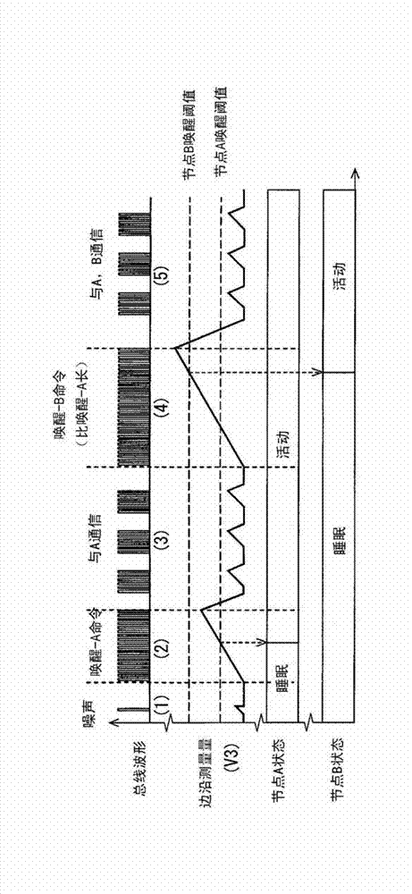
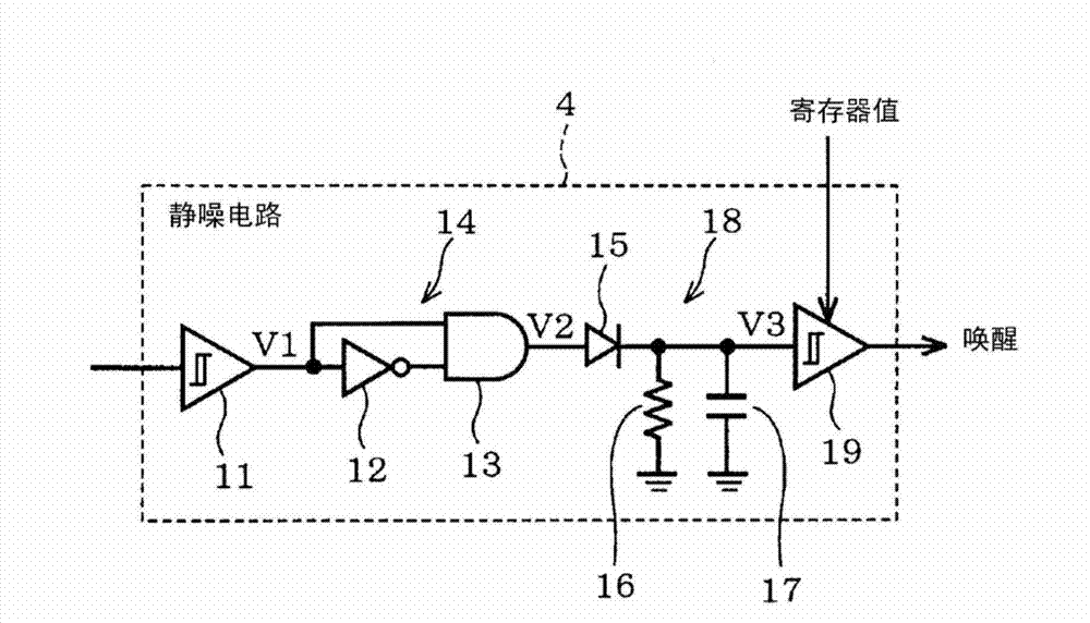
[0053] refer to Figure 1 to Figure 6 A first embodiment of the present invention will be described. see Figure 6 , the communication network system includes a communication bus 1 (ie, a communication line) and nodes 2A (ie, node A), 2B (ie, node B), and 2C (ie, node C) connected thereto. In the following, nodes 2A, 2B, 2C may be referred to as node 2 . Each of the nodes 2A, 2B, 2C is switchable such that the nodes 2A, 2B, 2C can be switched between two modes of operation, such as a normal mode / state of operation (i.e. active mode or active state) and Low power mode / state (i.e. sleep mode or sleep state). In the normal operation mode, each of the nodes 2A, 2B, 2C is controlled in an integral manner such that the control circuit of each of the nodes 2A, 2B, 2C ( Figure 4 ) has a clock signal provided to it for its operation. The control circuit 7 of each node 2A, 2B, 2C may be in the form of a CPU or a microcomputer. In the low power consumption mode, the operation of t...
no. 2 example )
[0075] Figure 7 to Figure 10 A second embodiment is shown, in which the description focuses on the differences from the first embodiment. In addition, the same parts have the same reference numerals, and descriptions of these same parts are omitted. refer to Figure 7 , the receiving unit 2Ra of the second embodiment includes a threshold setting register 8a, wherein the register value of the threshold setting register 8a can be changed by the control circuit 7a. When the control circuit 7a receives a threshold change command from the node 2 from the transmission side (ie, the transmission unit 2T), it writes the setting data added to the command into the threshold setting register 8a, and changes the threshold value change command in the squelch circuit 4 Schmitt trigger circuit 19 threshold. The remaining configuration of the configuration of the receiving unit 2Ra is the same as that of the first embodiment.
[0076] refer to Figure 8 to Figure 10 Advantageous effects...
no. 3 example )
[0086] refer to Figure 11 The third embodiment will be described, focusing on the differences from the second embodiment. The third embodiment describes the case where the threshold change of the squelch circuit 4 of the node 2B on the receiving side is performed based on the threshold change command sent by the node 2C. Node 2C starts up and communicates with nodes 2A and 2B, and after sending a threshold change command to node 2B, node 2C sends a sleep command. When the node 2B receives a threshold change command, the control circuit 7a of the node 2B rewrites the register value of the threshold setting register 8a of the node 2B according to the value specified by the command. Then, just like the second embodiment, by receiving the sleep command, the node 2B transitions to the sleep mode (see Figure 11 (1)-(8)).
[0087] As described above, since the change of the threshold value in the third embodiment is performed according to the change command sent by the node 2C o...
PUM
 Abstract
Description
Claims
Application Information
 - R&D Engineer
- R&D Manager
- IP Professional
- Industry Leading Data Capabilities
- Powerful AI technology
- Patent DNA Extraction
Browse by: Latest US Patents, China's latest patents, Technical Efficacy Thesaurus, Application Domain, Technology Topic, Popular Technical Reports.
© 2024 PatSnap. All rights reserved.Legal|Privacy policy|Modern Slavery Act Transparency Statement|Sitemap|About US| Contact US: help@patsnap.com


