Endoscope

An endoscope and bending technology, which is applied in the field of endoscopes, can solve problems such as difficulty in delivery, hooking and detachment of the front end part 201, and insertion obstacle of the insertion part 200.

Active Publication Date: 2013-01-02
OLYMPUS CORP
View PDF5 Cites 11 Cited by
  • Summary
  • Abstract
  • Description
  • Claims
  • Application Information

AI Technical Summary

Problems solved by technology

[0029] However, as shown in FIG. 20, when the insertion part 200 having the passive bending part 203 formed on the base end side of the active bending part 202 is used to lift the transverse colon P, since the passive bending part 203 is formed softly, The passive bending part 203 does not lift the transverse colon P and deflects, and when the bending angle is too large, when the front end part 201 is hooked on the transverse colon and pulled back to the insertion part, the front end part 201 is endowed with the opposite hooking effect. directional force, as a result, the front end 201 twists, and there is a problem that the front end 201 is hooked and detached.
[0030] and, if Figure 21A As shown, when the distal end portion 101 passes through the hepatic flexure Q of the transverse colon P, in a general endoscope provided with only the active bending portion 102, the distal end portion 101 reaches the flexure portion of the hepatic flexure Q , by rotating the insertion part 100 counterclockwise from the flexion part, the front end part 101 can pass through the hepatic flexure part Q, however, as Figure 21B As shown, in the endoscope provided with the passive bending part 203, when the passive bending part 203 is too curved, in the design process, the front end part 201 does not reach the flexure part of the hepatic curvature Q, and there is a need for the insertion part 200 thereafter. The insertion of the barrier problem
[0031] Further, such as As shown in Figure 22, when the insertion part 200 passes through the sigmoid colon S, in an endoscope provided with a passive bending part 203, when the passive bending part 203 is too curved, due to the force applied to the insertion part 200 It is reversed from S1 to S2, so there is a problem that it is difficult to transmit the advancing force from the base end side of the insertion part 200 to the front end part 201 well.

Method used


Image

  • Endoscope
  • Endoscope
  • Endoscope

Examples


Embodiment Construction

[0065] Hereinafter, embodiments of the present invention will be described with reference to the drawings. In addition, the drawings are schematic, and it should be noted that the relationship between the thickness and width of each component, the ratio of the thickness of each component, etc. are different from reality, and of course there are also differences in the relationship and ratio of dimensions between the drawings. part.

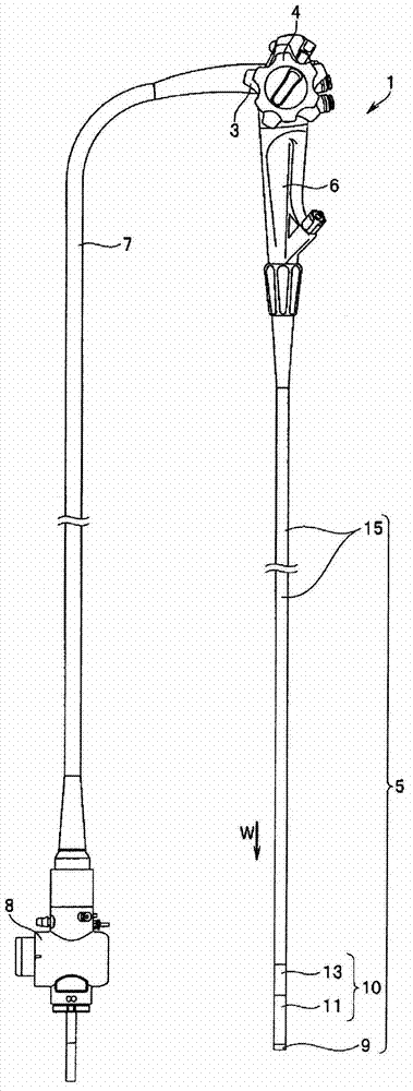
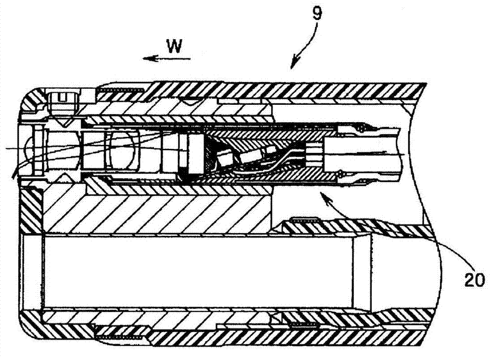
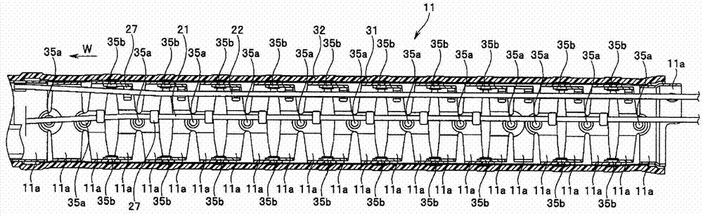
[0066] figure 1 It is a figure showing the endoscope of this embodiment, figure 2 is in figure 1 A partial cross-sectional view of the tip portion provided in the insertion portion of the endoscope, image 3 is in figure 1 Partial cross-sectional view of the active bending part provided in the insertion part of the endoscope, Figure 4 is shown in figure 1 A partial cross-sectional view near the connection site of the active bending part and the passive bending part provided in the insertion part of the endoscope, Figure 5 is in fig...


PUM


Abstract

An endoscope comprises: an active bendable section (11) provided to an insertion section and capable of bending according to bending operation, the active bendable section (11) having adjacent bending elements (11a) pivotably connected to each other by pivot shafts (35a, 35b), the pivot shafts (35a, 35b) being provided at positions displaced from each other by 90 DEG in the circumferential direction (J) of the bending elements (11a); and passive bendable sections (13) provided to the insertion section so as to be closer to the proximal end side than the active bendable section (11) and capable of passively bending when subjected to an external force, the passive bendable sections (13) having adjacent bending elements (13a) pivotably connected to each other by pivot shafts (45a-45c), the pivot shafts (45a-45c) being provided at positions displaced from each other by 60 DEG in the circumferential direction (J).

Description

technical field [0001] The present invention relates to an endoscope having an insertion portion inserted into a subject. Background technique [0002] In recent years, endoscopes have been widely used in the medical and industrial fields. The endoscope used in the medical field can observe the organs in the body cavity by inserting the elongated insertion part into the body cavity of the subject, and if necessary, use the Various treatments are performed through the treatment instrument inserted into the channel. [0003] In addition, the endoscope used in the industrial field can be used to damage and repair the parts to be inspected in the object by inserting the elongated insertion part of the endoscope into the object to be inspected, such as jet engine or factory piping. Observation of corrosion, etc., inspection of various treatments, etc. [0004] Usually, a plurality of bending pieces are connected so as to be rotatable along the insertion direction on the front ...

Claims


Application Information

Patent Timeline
Patent Type & Authority Applications(China)
IPC IPC(8): A61B1/00G02B23/24
CPCA61B1/0055G02B23/2476A61B1/0056
Inventor 冈庭杰
Owner OLYMPUS CORP
Why Eureka
Try Eureka