Supercharge Your Innovation With Domain-Expert AI Agents!

Semiconductor chip removal device using laser and method for removing semiconductor chip

A semiconductor and chip technology, used in laser welding equipment, semiconductor devices, single semiconductor device testing, etc., it can solve the problems of manual labor, the lack of standardization of traditional technology, and the dependence on engineers, and achieve the effect of minimizing thermal damage

Active Publication Date: 2016-06-01
SAMSUNG ELECTRONICS CO LTD
View PDF4 Cites 1 Cited by
  • Summary
  • Abstract
  • Description
  • Claims
  • Application Information

AI Technical Summary

Problems solved by technology

However, conventional techniques for removing failed semiconductor chips are not standardized and rely on the manual labor of engineers

Method used


Image

  • Semiconductor chip removal device using laser and method for removing semiconductor chip
  • Semiconductor chip removal device using laser and method for removing semiconductor chip
  • Semiconductor chip removal device using laser and method for removing semiconductor chip

Examples


Embodiment Construction

[0025] Embodiments of the inventive concept will be described more fully hereinafter with reference to the accompanying drawings, in which embodiments of the invention are shown. However, inventive concepts may be embodied in many different forms and should not be construed as limited to the example embodiments set forth herein. Rather, these embodiments are provided so that this disclosure will be thorough and complete, and will fully convey the scope of the inventive concept to those skilled in the art. In the drawings, the size and relative sizes of layers and regions are exaggerated for clarity. The same reference numerals denote the same elements throughout.

[0026] The terminology used herein is for the purpose of describing particular embodiments only and is not intended to be limiting of the invention. As used herein, the singular forms "a", "an" or "the" are intended to include the plural forms as well, unless the context clearly dictates otherwise. It should also...


PUM

PropertyMeasurementUnit
diameteraaaaaaaaaa

Abstract

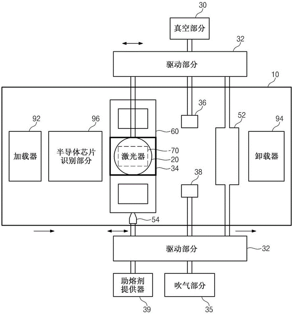
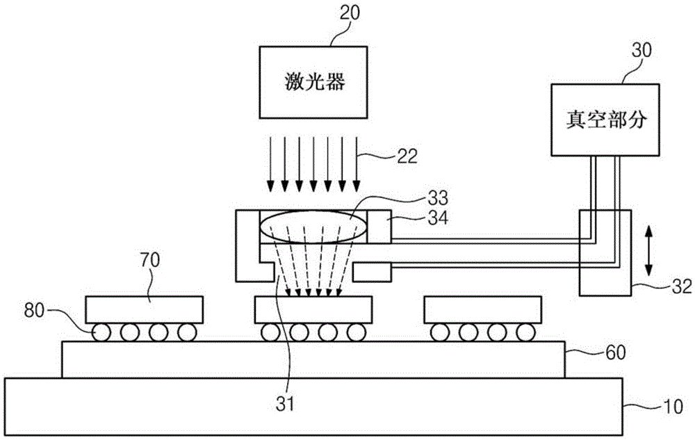
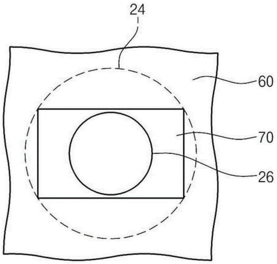
The present invention discloses a semiconductor chip removing apparatus capable of minimizing damage to a board and a method of removing a semiconductor chip. The semiconductor chip removal apparatus may include: a table for supporting a board on which the semiconductor chip is mounted via bumps; a laser that irradiates a laser beam into an area of ​​the board larger than the semiconductor chip; and a picker that The laser beam is caused to locally penetrate the semiconductor chip and the semiconductor chip heated by the laser beam is separated from the plate.

Description

technical field [0001] The inventive concepts herein relate to semiconductor manufacturing apparatuses and methods of manufacturing semiconductors, and in particular, to apparatuses for removing failed semiconductor chips from a board and methods of removing failed semiconductor chips from a board. Background technique [0002] Recently, among printed circuit boards (PCBs), there has been an increasing demand for boards manufactured by a flip-chip method. A board manufactured by the flip chip method is a board whose functional characteristics and electrical characteristics are improved by connecting semiconductor chips and the board with solder bumps instead of existing wiring. After the product has passed the mounting test as one of the module processes, the board manufactured by the flip chip method can be shipped. After the failed semiconductor chip is removed from the board, the product that failed the mounting test can be repaired. However, conventional techniques for...

Claims


Application Information

Patent Timeline
Patent Type & Authority Patents(China)
IPC IPC(8): B23K3/00B23K1/018H01L21/67
CPCB23K1/0016B23K1/0056B23K1/018B23K2101/42H01L24/799H01L24/98H01L2224/131H01L2224/16225H01L2224/16227H01L2924/12042H05K13/0486Y10T29/49821Y10T29/53274H01L2924/014H01L2924/00G01R31/26H01L22/00B23K26/38
Inventor 朴在用高濬泳申和秀郑基贤
Owner SAMSUNG ELECTRONICS CO LTD
Features
  • R&D
  • Intellectual Property
  • Life Sciences
  • Materials
  • Tech Scout
  • Unparalleled Data Quality
  • Higher Quality Content
  • 60% Fewer Hallucinations
Learn More