

Anti-seepage sleeve of gear shaft
A technology of gear shaft and sleeve body, applied in the direction of coating, furnace type, furnace, etc., can solve the problems of waste of energy, increase of labor, deviation of anti-seepage area, etc., to improve the quality of anti-seepage, improve production efficiency, and save energy Effect
Inactive Publication Date: 2013-01-09
江国辉
View PDF2 Cites 10 Cited by
- Summary
- Abstract
- Description
- Claims
- Application Information
AI Technical Summary
Problems solved by technology
Carburizing and quenching after coating the anti-seepage agent on the thread increases the amount of labor, and the anti-seepage agent is a fluid substance, which may cause deviations in the anti-seepage area, which cannot achieve product consistency, and the appearance of the product has obvious anti-seepage Traces; using intermediate frequency quenching after carburizing and quenching also increases the process and requires investment in intermediate frequency equipment, which requires high equipment and personnel, and intermediate frequency annealing wastes energy
Method used
View moreImage
Smart ImageViewing Examples

Examples
Embodiment Construction
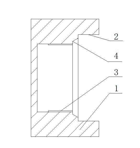
[0008] The invention provides a gear shaft anti-seepage sleeve, which includes a sleeve body 1, the sleeve body 1 is cylindrical, and a circle 2 is arranged at the opening of the sleeve body 1, and the length of the circle 2 is half of the excessive hardness area of the drive shaft. The bottom of sleeve body 1 is provided with thread 3, and thread 3 is threadedly matched with driving shaft, and step 4 is arranged between described thread 3 and circle 2, and step 4 closely cooperates with the step of thread on the driving shaft.
Login to View More PUM
 Abstract
The invention discloses an anti-seepage sleeve of a gear shaft. The anti-seepage sleeve comprises a sleeve body (1), wherein a circle (2) is arranged at an opening of the sleeve body (1); the bottom of the sleeve body (1) is provided with a thread (3); and a step (4) is arranged between the thread (3) and the circle (2). The anti-seepage sleeve of the gear shaft, which is used in quenching, has the advantages of being convenient to mount and improved in anti-seepage quality, increasing the production efficiency and saving energy.
Description
technical field [0001] The invention relates to a gear shaft anti-seepage sleeve. Background technique [0002] In the process of manufacturing automobile gear shafts, heat treatment is a necessary process. In order to improve the surface wear resistance, fatigue strength, and core toughness of the gear shaft, carburizing and quenching is usually used, and the hardness of the threaded part must be controlled to ensure that it cannot exceed 38HRC to ensure the toughness of the thread and avoid the breakage of the thread. and fractures at the thread. Now, in order to control the thread hardness, it is usually used to apply anti-seepage agent on the thread and then carburize and quench, or to anneal at the thread section after carburizing and quenching. Carburizing and quenching after coating the anti-seepage agent on the thread increases the amount of labor, and the anti-seepage agent is a fluid substance, which may cause deviations in the anti-seepage area, which cannot ach...
Claims
Login to View More Application Information
Patent Timeline
 Patent Type & AuthorityApplications(China)
IPC IPC(8): C23C8/04C21D9/28
Inventor江国辉
Owner江国辉