Combing machine cylinder structure with built-in nipper assemblies

A technology of combing machine and nipper, applied in the direction of combing machine, textile and papermaking, fiber processing, etc., can solve the problems of complex movement, low work efficiency, high noise, etc., achieve simple movement form, improve carding efficiency, noise small effect

Inactive Publication Date: 2015-01-07
DONGHUA UNIV
View PDF8 Cites 2 Cited by
  • Summary
  • Abstract
  • Description
  • Claims
  • Application Information

AI Technical Summary

Problems solved by technology

[0004] The technical problem to be solved by the present invention is to provide a combing machine cylinder structure with a built-in nipper assembly, which can realize reliable combing, transfer and joining of fibers, and overcome the complex movement and low work efficiency existing in the prior art , loud noise, etc.

Method used


Image

  • Combing machine cylinder structure with built-in nipper assemblies
  • Combing machine cylinder structure with built-in nipper assemblies
  • Combing machine cylinder structure with built-in nipper assemblies

Examples


Embodiment Construction

[0019] Below in conjunction with specific embodiment, further illustrate the present invention. It should be understood that these examples are only used to illustrate the present invention and are not intended to limit the scope of the present invention. In addition, it should be understood that after reading the teachings of the present invention, those skilled in the art can make various changes or modifications to the present invention, and these equivalent forms also fall within the scope defined by the appended claims of the present application.

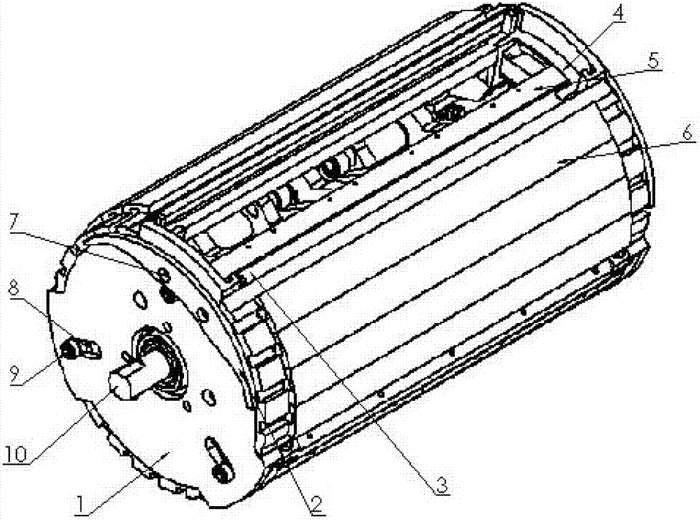
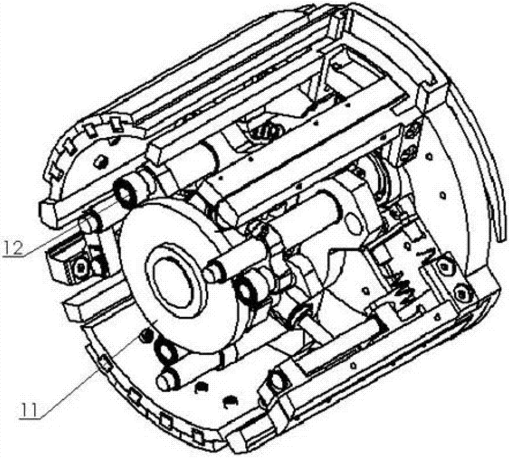
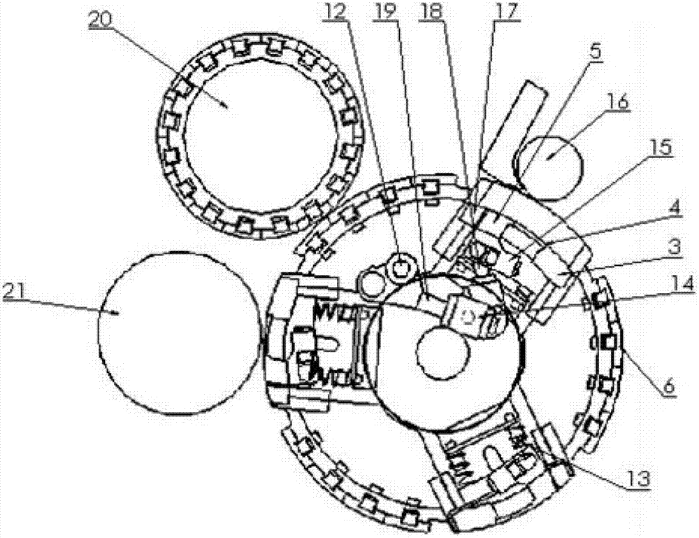
[0020] Such as Figure 1 ~ Figure 3 Shown, the present invention comprises cylinder shaft 10, cylinder, cylinder end cover 1, nipper assembly, cylinder comb device 6, and described cylinder shaft 10 is fixed on the frame of combing machine, and described tin The looper is set on the cylinder shaft 10, and the two ends of the cylinder shaft 10 are respectively fixed with cylinder end caps 1, 1 to 4 sets of nipper assemblies and...


PUM


Abstract

The invention relates to a combing machine cylinder structure with built-in nipper assemblies. The combing machine cylinder structure comprises a cylinder shaft, a cylinder, cylinder end caps, the nipper assemblies and a cylinder card wire device, wherein the cylinder is movably sleeved on the cylinder shaft; the cylinder end caps are respectively fixed at two ends of the cylinder shaft; 1-4 nipper assemblies and the cylinder card wire device are peripherally distributed on the periphery of the cylinder uniformly; and each nipper assembly comprises a movable nipper, a fixed nipper, a nipper stretching and retracting mechanism, a nipper pressurizing mechanism and a nipper driving mechanism, the movable nipper is mounted on the nipper stretching and retracting mechanism and is connected with the nipper driving mechanism through the nipper pressurizing mechanism, and the fixed nipper is fixed on the nipper stretching and retracting mechanism. Combing and piecing modes finished in a narrow triangular region in the traditional combing process actions is changed into a mode that combing and piecing are simultaneously carried out on different portions of the surface of the periphery of the cylinder. After the cylinder rotates by a circle, a plurality of combing processes can be finished, and the combining efficiency of a combing machine is greatly improved. The combing machine cylinder structure is simple in motion mode, low in noise and suitable for popularization and application.

Description

technical field [0001] The invention belongs to the technical field of spinning machinery, in particular to a combing machine cylinder structure with a built-in nipper assembly. Background technique [0002] Existing cotton combing machines rely on the reciprocating motion of mechanisms such as complex ratchets, connecting rods and gears to realize the carding process. The intermittent feeding of the cotton roller, the reciprocating swing of the combing nipper and the top comb, and the reversing, smoothing, and stopping cycles of the separation roller will directly cause equipment vibration and noise. It is difficult to further improve the combing machine in this working mode. Nippers for cotton combing machines. [0003] German Truetzschler company discloses a kind of drum type combing machine in the patent that publication number is CN101333701A, and the combing machine of this patent is arranged with dozens of nippers on the drum, adopts grouping to clamp fiber The meth...

Claims


Application Information

Patent Timeline
Patent Type & Authority Patents(China)
IPC IPC(8): D01G19/10
Inventor 毛立民侯春杰张洪谢征恒裴泽光裴会成桂柏平
Owner DONGHUA UNIV
Why Eureka
Try Eureka