Backlight module and light-emitting diode (LED) display

A technology of backlight module and light source module, applied in the field of LED display, can solve the problems of reducing luminous efficiency, shadow of backlight module, light leakage of liquid crystal screen, etc., and achieve the effect of improving backlight effect, improving heat dissipation efficiency and eliminating dark area.

Active Publication Date: 2013-01-09
创维集团智能科技有限公司
View PDF8 Cites 19 Cited by
  • Summary
  • Abstract
  • Description
  • Claims
  • Application Information

AI Technical Summary

Problems solved by technology

[0003] 1. LED in high temperature environment, the luminous efficiency is reduced, and the life is shortened
In the actual design, the designer has to deliberately reduce the working current of the LED to reduce the heat generated by the backlight module per unit time, so that the LED system is not in the best driving state, which reduces the luminous efficiency and improves the backlight module system solution. the cost of
[0004] 2. The optical film and light guide plate in the backlight module are easily deformed at high temperature, resulting in local shadows and uneven brightness and darkness in the backlight module. In addition, the liquid crystal screen is prone to light leakage at high temperature, which affects the viewing effect
[0005] 3. In order to solve the heat dissipation problem, the module design has to use high-cost aluminum backplane, heat dissipation glue and heat dissipation aluminum plate. Some manufacturers even use a water cooling system or embed a heat dissipation fan inside the module, which increases the cost. cost, and brings difficulties to the structural design and light weight of the backlight module
In the traditional backlight module, the LED light source is directly introduced into the backlight module from the side of the light guide plate, without sufficient light mixing, so dark areas will be generated on the light incident side of the backlight module

Method used


Image

  • Backlight module and light-emitting diode (LED) display
  • Backlight module and light-emitting diode (LED) display

Examples


Embodiment Construction

[0020] It should be understood that the specific embodiments described here are only used to explain the present invention, not to limit the present invention.

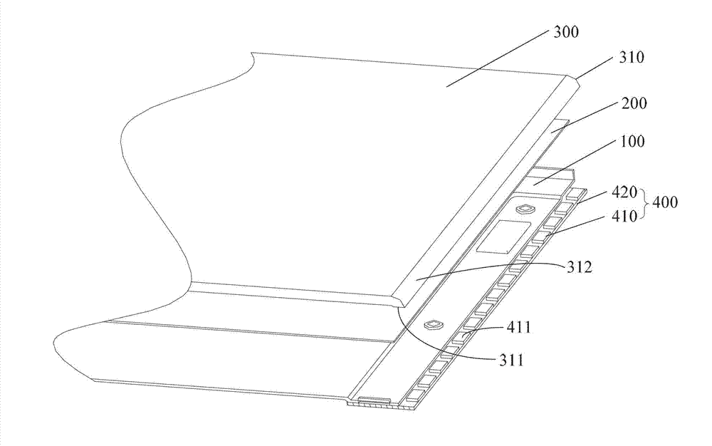
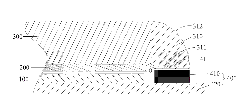
[0021] see Figure 1-Figure 2 A preferred embodiment of the backlight module of the present invention is shown, the backlight module includes a light source module 400 with a light-emitting surface and a backplane 100, a reflection sheet 200, and a light guide plate 300 stacked in sequence, and the light guide plate One end of 300 is bent and extended toward the backplane 100 to form a bent part 310 with an outer surface 312 that is opaque. The light-emitting surface 411 is set opposite to the light-incident surface 311 , and it is best to be in close contact in order to reduce the loss of the light source. That is, as shown in the figure, the light incident surface of the light source module is not facing the side of the light guide plate as in the prior art, but faces the back of the light guide plate. The bending...


PUM


Abstract

The invention discloses a backlight module and a light-emitting diode (LED) display. The backlight module comprises a light source module with a luminous surface and a back panel, a reflecting piece and a light guide plate which are sequentially stacked, wherein one end of the light guide plate bends and extends to the back panel direction to form a bending part of which the outer surface is not transparent; an end face at the tail end of the bending part is a light entrance surface; and the light source module is fixed on the edge of the back panel, and the luminous surface of the light source module is opposite to the light entrance surface. According to the backlight module, because the light source module is positioned on the outer side of the back panel, the generated heat is directly dispersed outwards and is not collected inside the back panel; and therefore, the radiating efficiency is improved, and all problems caused by bad radiation of the backlight module in the traditional technology are solved; and meanwhile, the light source emitted from the light source module does not directly enter the side face of the light guide plate and enters the light entrance surface of the bending part, after the light is reflected and fully mixed inside the bending part, and the light source enters the backlight module; and therefore, the dark space inside the backlight module is eliminated, and the backlight effect is improved.

Description

technical field [0001] The invention relates to the technical field of LED displays, in particular to a backlight module and an LED display. Background technique [0002] The heat dissipation problem of LED backlight modules has always troubled the technicians in the industry. The reason is that the edge of the backplane in the traditional backlight module is usually provided with a support plate, and the light source module is fixed on the support plate inside the backplane. As a result, the internal parts of the backlight module are closely arranged, the space is narrow, and the heat generated by the LED cannot be dissipated in time, thus causing many problems, such as: [0003] 1. Under high temperature environment, the luminous efficiency of LED is reduced and the life is shortened. In the actual design, the designer has to deliberately reduce the working current of the LED to reduce the heat generated by the backlight module per unit time, so that the LED system is not...

Claims


Application Information

Patent Timeline
Patent Type & Authority Applications(China)
IPC IPC(8): F21S8/00F21V29/00F21V19/00G09F9/33F21Y101/02F21V29/503F21V29/60
Inventor 朋朝明
Owner 创维集团智能科技有限公司
Why Eureka
Try Eureka