
Fiber Bragg grating strain sensor

A grating strain and sensor technology, which is applied in the direction of instruments, optical devices, measuring devices, etc., can solve the problems of small measurement range of strain sensors and complicated installation process, and achieve the effect of small solder joints, not easy to fall off, and firm welding

Inactive Publication Date: 2013-01-09
杭州珏光物联网科技有限公司
View PDF8 Cites 26 Cited by
  • Summary
  • Abstract
  • Description
  • Claims
  • Application Information

AI Technical Summary

Problems solved by technology

[0004] The purpose of the present invention is to overcome the problems of small measurement range and complicated installation process of the strain sensor in the prior art, and provide a fiber Bragg grating strain sensor based on a cylindrical elastic structure with alternating holes

Method used


Image

  • Fiber Bragg grating strain sensor
  • Fiber Bragg grating strain sensor
  • Fiber Bragg grating strain sensor

Examples


Embodiment Construction

[0020] The present invention will be further described below in conjunction with the accompanying drawings, but they do not constitute a limitation to the present invention, but are only examples to make the advantages of the present invention more clear and easy to understand. Fixed structure, sealing interface and supporting base.

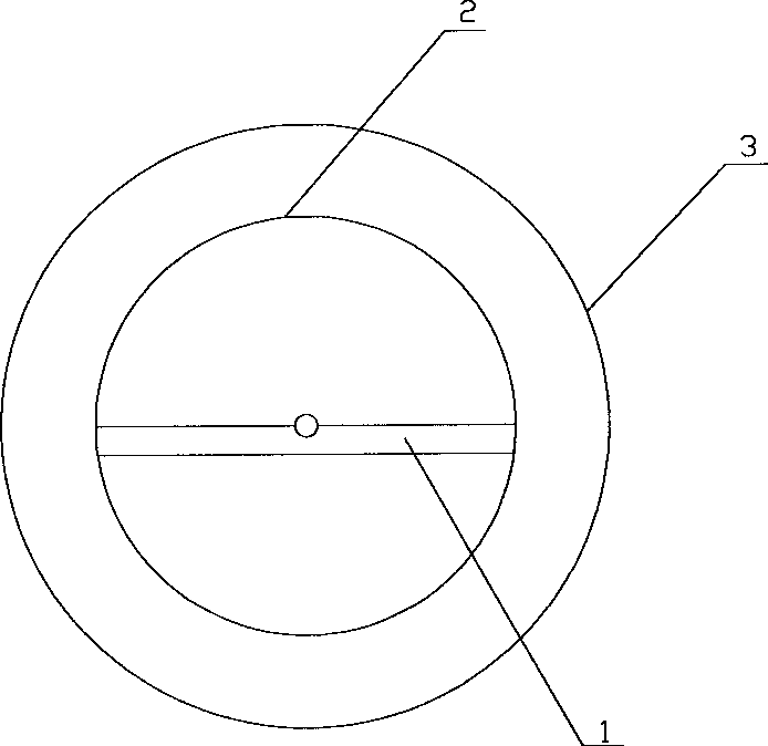
[0021] like figure 1 , figure 2 , image 3 and Figure 4 As shown, the fiber Bragg grating strain sensor includes an elastic structure 4 with holes alternately spaced, a fiber Bragg grating 5, a protective sleeve 6, a sealing ring 7, a fixed structure 8, and a sealing interface 9; the elastic structure 4 includes an elastic region 3, a metal sheet 1 and thread 2, and the elastic area 3, metal sheet 1 and thread 2 are integrated structures; the cavities constituting the elastic area 3 are perpendicular to the central axis of the cylinder, and cross the central axis of the cylinder, and are distributed in the elastic in a staggered manner. Str...


PUM


Abstract

The invention relates to a fiber Bragg grating strain sensor which comprises an elastic structure, an optical fiber grating, protective sleeves, sealing rings, fixed structures and sealing joints. The elastic structure comprises an elastic area with alternately spaced cavities, metal sheets and thread screws. The elastic area, the metal sheets and the thread screws are in an integral structure. The cavities forming the elastic area are vertical to the central axis of a cylinder, pass over the central axis of the cylinder and are distributed on the elastic structure in a staggered arrangement manner. Both ends of the elastic structure are in threaded connection with the fixed structures. The metal sheets are arranged in the fixed structures. The other ends of the fixed structures are in threaded connection with one ends of the sealing joints for fixing armored jackets. Both ends of the fiber Bragg grating passing through the central axis of the elastic structure are fixedly arranged on protruding metal sheets at both ends of the elastic structure by glass solder. The sealing rings arranged at the inner side of the thread screws of the fixed structures and the protective sleeves seal the elastic area. When the sensor is buried, the fixed structure is a flange structure. The fiber Bragg grating strain sensor provided by the invention has the advantages of large measuring range and simpleness in installation.

Description

technical field [0001] The invention belongs to the technical field of optical fiber sensing and relates to an optical fiber Bragg grating strain sensor. Background technique [0002] With the advancement of science and technology, electronic sensors are susceptible to electromagnetic interference and complex in structure, unable to distribute measurement and remote monitoring, and can no longer meet the requirements of today's society. In recent years, fiber Bragg grating sensors have been widely used in safety and health monitoring of structural engineering such as dams, bridges, tunnels and petrochemical industries due to their advantages of anti-electromagnetic interference, integration of sensing and transmission, and simple structure. [0003] The fiber Bragg grating strain sensor is used to monitor the small changes of the object to be measured, and has a wide range of applications. In recent years, fiber Bragg grating strain sensors have been well developed. In the...

Claims


Application Information

Patent Timeline
Patent Type & Authority Applications(China)
IPC IPC(8): G01B11/16
Inventor 陈庆根罗宗胜王云鹏
Owner 杭州珏光物联网科技有限公司
Learn More