
Spline curve compensation method for measuring profile deviation based on path unit

A technology of spline curve and path unit, which is applied in the field of CNC machining, can solve the problems of high cost, affecting surface quality, and long time consumption, so as to meet the requirements of high-precision and high-speed machining, avoid the inflection point of the rough path, and reduce the production cost.

Active Publication Date: 2013-01-09
BEIJING JINGDIAO GRP CO LTD
View PDF6 Cites 18 Cited by
  • Summary
  • Abstract
  • Description
  • Claims
  • Application Information

AI Technical Summary

Problems solved by technology

[0003] At present, the CNC system generally adopts the macro program method to realize the path compensation of the measurement contour. Due to the limitation of the program itself, the macro program cannot consider the relationship between the measurement points as a whole when calculating, and can only perform two adjacent measurement points. The calculation between, therefore, its error curve can only be done in a linear way
In this way, when there is a large deviation between the actual measured position and the reference position, a small inflection point of the path may appear at the measurement node, resulting in ribs on the processed surface during processing, which affects the surface quality
In order to reduce the occurrence of the inflection point, it is necessary to increase the measurement point or control the deformation of the incoming material and improve the accuracy of the tooling to reduce the deviation, which virtually increases the production cost; in addition, in the initial stage of process debugging, it is usually necessary to carry out macro program Repeated debugging, which not only requires high technical personnel, but also takes a long time and costs a lot

Method used


Image

  • Spline curve compensation method for measuring profile deviation based on path unit
  • Spline curve compensation method for measuring profile deviation based on path unit
  • Spline curve compensation method for measuring profile deviation based on path unit

Examples


Embodiment Construction

[0018] The present invention will be further described in detail below in conjunction with the accompanying drawings and specific embodiments.

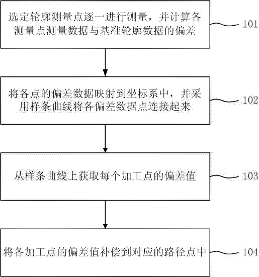
[0019] Such as figure 1 Shown, the spline curve compensation method of the measurement profile deviation based on path unit of the present invention, comprises the following steps:

[0020] In step 101, the selected contour measurement points are measured one by one, and the deviation between the measurement data of each measurement point and the reference contour data is calculated.

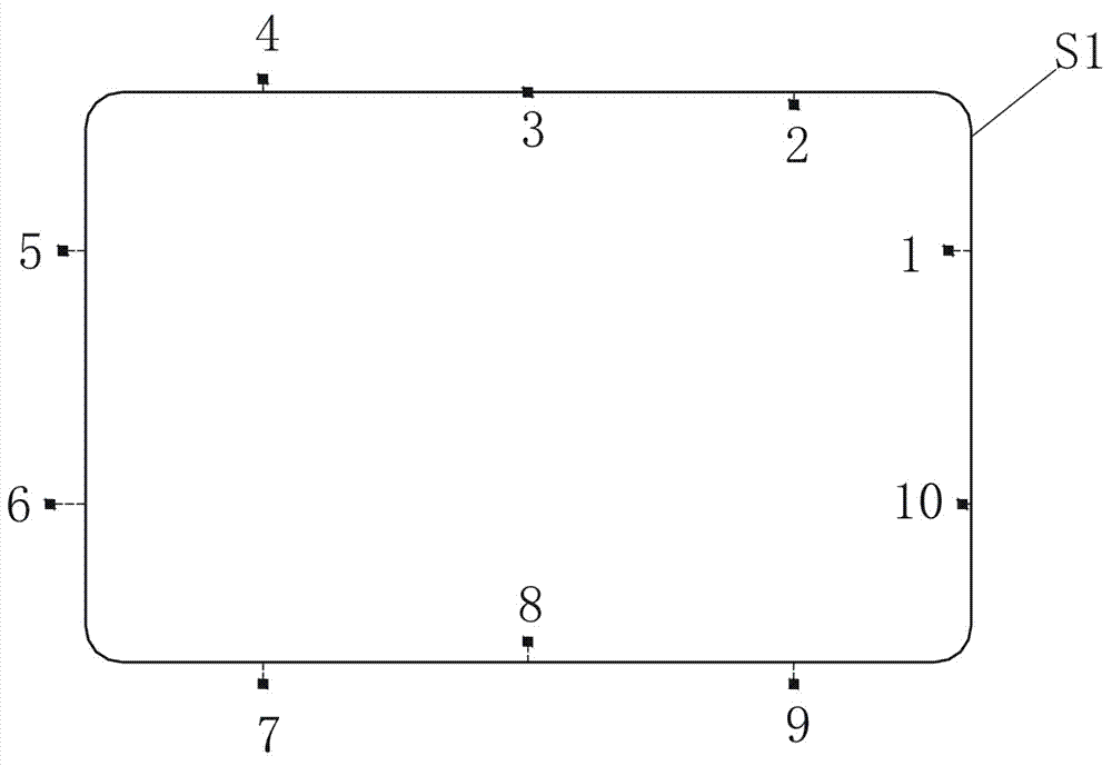
[0021] figure 2 It shows a schematic diagram of measuring the contour of a square workpiece. Ten measuring points are selected on the reference contour curve S1, and points 1 to 10 are the actual measured positions of the ten measuring points.

[0022] image 3 Explained the calculation method of the deviation between the measurement data of the measurement point and the reference contour data, that is, the deviation value △ε=±the vertical distance ...


PUM


Abstract

The invention belongs to the technical field of numerical control machining, and particularly relates to a spline curve compensation method for measuring profile deviation based on a path unit. The method comprises the following steps: selecting profile measurement points, measuring the profile measurement points one by one, and calculating the deviations between the measurement data of the measurement points and the standard profile data; mapping the calculated deviation data of the measurement points to a coordinate system, and connecting the deviation data points together with a spline curve; acquiring the deviation value of each of machining points from the spline curve; and compensating the deviation values to corresponding path points. According to the invention, the path unit is used as the object and the mode of spline error compensation is used to effectively avoid unsmooth inflection points of the path caused by a linear method, so that a compensation path can be more smooth, the high-precision and high-speed machining requirements can be met, a better surface effect can be acquired, and the path compensation can be carried out on a work piece with relatively large deformation; and the method is simple and easy to use, the programming efficiency is high, and the production cost can be effectively lowered.

Description

technical field [0001] The invention belongs to the technical field of numerical control machining, and in particular relates to a spline curve compensation method for measuring contour deviation based on path units. Background technique [0002] When machining contours such as chamfering, in order to ensure the processing accuracy and consistency of batch processing of products, a specific fixture is usually selected for positioning; this positioning method has high requirements for fixtures and operators. If there is a position or angle deviation, or If the workpiece is deformed by force, the processed product will have quality problems such as inconsistent chamfer width, which will affect the aesthetics of the product and the pass rate of the product. With the continuous improvement of product accuracy requirements, contour measurement compensation technology has emerged on the basis of fixture positioning, that is, after product positioning and clamping, the contour of t...

Claims


Application Information

Patent Timeline
IPC IPC(8): G01B21/20
Inventor 蔡锐龙孙艺华
Owner BEIJING JINGDIAO GRP CO LTD
Learn More