Plane static pressure type vibration transferring and decoupling device and tri-axial vibration composite experiment table

A decoupling device and plane technology, applied in the field of mechanical environment test equipment, can solve problems such as poor reliability, short service life, and easy distortion of thrust, and achieve the effect of large anti-overturning moment, strong bearing capacity, and strong decoupling ability

Active Publication Date: 2013-01-09
SUZHOU SUSHI TESTING INSTR CO LTD
View PDF11 Cites 25 Cited by
  • Summary
  • Abstract
  • Description
  • Claims
  • Application Information

AI Technical Summary

Problems solved by technology

Although the above-mentioned patent uses a linear guide rail as a vibration transmission decoupling device, although the structure is simple and easy to implement, it has the following disadvantages: First, due to the gap in the linear guide rail, the rigidity in the transmission direction is poor, and the transmission vibration frequency and thrust are easily distorted, especially The distortion is great

Method used


Image

  • Plane static pressure type vibration transferring and decoupling device and tri-axial vibration composite experiment table
  • Plane static pressure type vibration transferring and decoupling device and tri-axial vibration composite experiment table
  • Plane static pressure type vibration transferring and decoupling device and tri-axial vibration composite experiment table

Examples


Embodiment 1

[0060] Example 1: A Triaxial Vibration Composite Test Bench

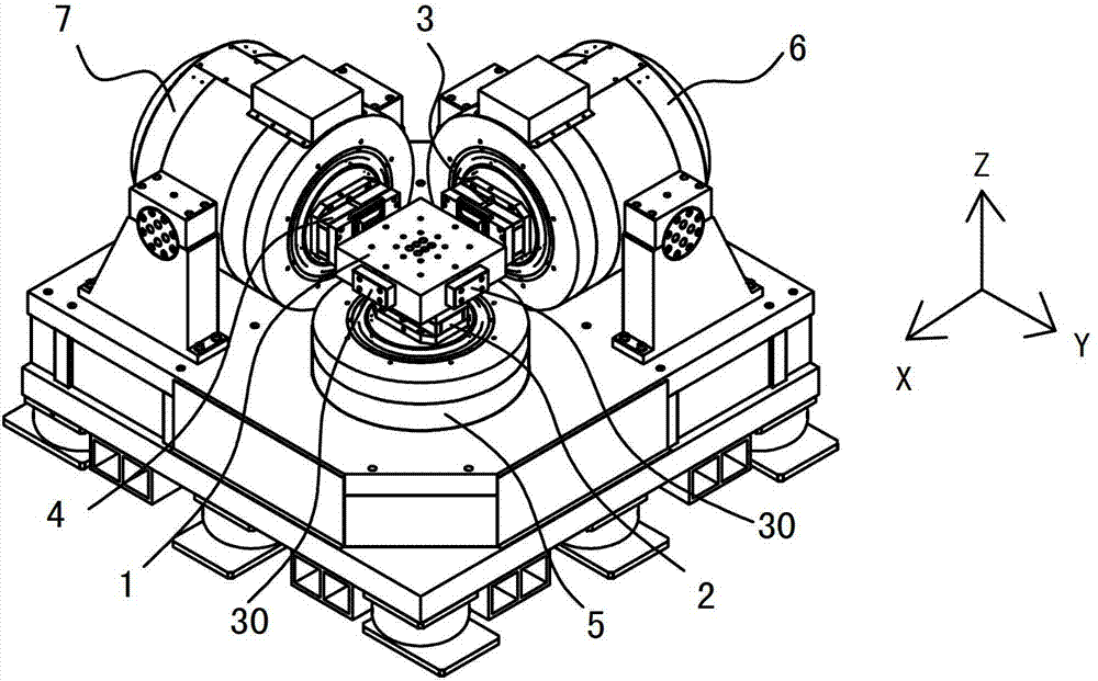
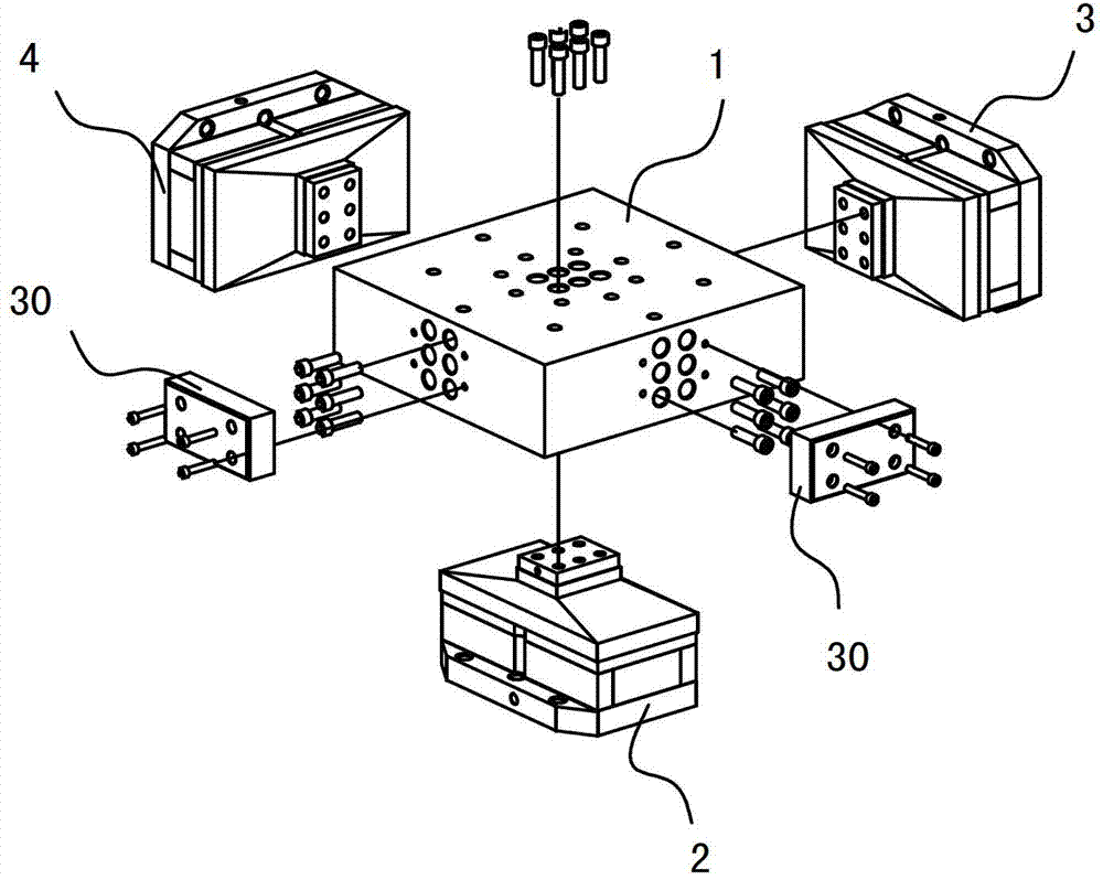
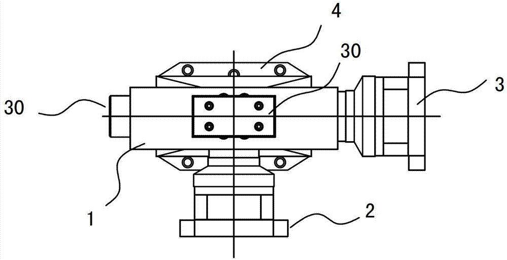
[0061] Such as Figure 1-5 As shown, the three-axis vibration composite test bench has a worktable 1 for carrying test objects, and the worktable 1 is connected to a Z-axis vibration decoupling device 2 through a Z-axis vibration decoupling device 2 in the vertical Z-axis direction at the bottom. The generator 5 is connected to an X-axis vibration generator 6 through an X-axis vibration decoupling device 3 in the horizontal X-axis direction on the side, and is connected to an X-axis vibration generator 6 in the horizontal Y-axis direction on the side through a Y-axis vibration decoupling device 4. Connect a Y-axis vibration generator 7.

[0062] The X-axis vibration generator 6, the Y-axis vibration generator 7 and the Z-axis vibration generator 5 can adopt an electric vibration table, a mechanical vibration table, a hydraulic vibration table or a mechanical vibration mechanism, wherein the mechanical vibration mec...

Embodiment 2

[0084] Example 2: A planar static pressure vibration transmission decoupling device

[0085] The planar static pressure vibration transmission decoupling device can be applied to a two-axis vibration compound test bench or a three-axis vibration compound test bench. Its structure is the same as that of the planar static pressure vibration-transmitting and decoupling device described in Embodiment 1, and will not be described again here. Please refer to the relevant content of Embodiment 1.


PUM


Abstract

The invention relates to a tri-axial vibration composite experiment table and a plane static pressure type vibration transferring and decoupling device, wherein the experiment table comprises a working table top; and plane static pressure type vibration transferring and decoupling devices and vibration generators are connected in the direction of X, Y and X axes of the work table top. The plane static pressure type vibration transferring and decoupling device is characterized by consisting of a sliding block and a sliding seat via sliding connection; a sliding gap is arranged in a sliding surface; during the work, high-pressure oil is filled in the sliding gap through an oil filling channel to form a static pressure oil slick; as the static pressure oil slick has good rigidity under high pressure conditions, the sliding between the sliding block and the sliding seat is not obstructed. When a coaxial vibration generator generates high-frequency vibration and thrust, the vibration frequency and the thrust are transferred through a direction vertical to the static pressure oil slick; when a hetero-axial vibration generator generates high-frequency vibration and thrust, the decoupling is realized through the sliding between the sliding block and the sliding seat, so that the aim of combining the lossless transferring and the effective decoupling is realized to the greatest extent.

Description

technical field [0001] The invention relates to mechanical environment test equipment, in particular to a test bench for realizing X, Y, Z three-axis vibration compounding and a vibration transmission decoupling device in the test bench. The test bench can be used to realize the vibration environment in which the three axes of X, Y, and Z work independently, and can also be used to realize the compound vibration environment in which any two axes or the three axes of X, Y, and Z work simultaneously. Background technique [0002] The purpose of the vibration test is to artificially simulate the vibration load that the product may experience during transportation, storage and use and its impact on the test piece in the laboratory, and to assess its adaptability. The conventional test method is to use uniaxial vibration test equipment to excite the product in a certain direction. However, in the actual natural environment, the vibration and shock that the product suffers is a c...

Claims


Application Information

Patent Timeline
IPC IPC(8): G01M7/06
Inventor 郑建洲武元桢
Owner SUZHOU SUSHI TESTING INSTR CO LTD
Why Eureka
Try Eureka