Automotive gasoline solenoid double pole direct injector

A direct, fuel injector technology that can be used in injection devices, fuel injection devices, machines/engines, etc., to solve problems such as increasing costs

Active Publication Date: 2013-01-09
VITESCO TECH USA
View PDF6 Cites 4 Cited by
  • Summary
  • Abstract
  • Description
  • Claims
  • Application Information

AI Technical Summary

Problems solved by technology

These conventional direct injectors are not configured in a modular fashion and thus cannot be constructed and tested in modular stages
This leads to scrap during manufacturing and thus increases costs

Method used


Image

  • Automotive gasoline solenoid double pole direct injector
  • Automotive gasoline solenoid double pole direct injector
  • Automotive gasoline solenoid double pole direct injector

Examples


Embodiment Construction

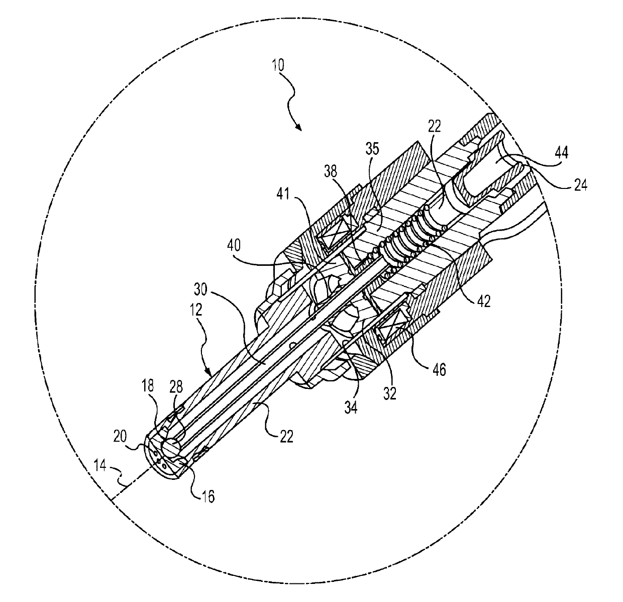
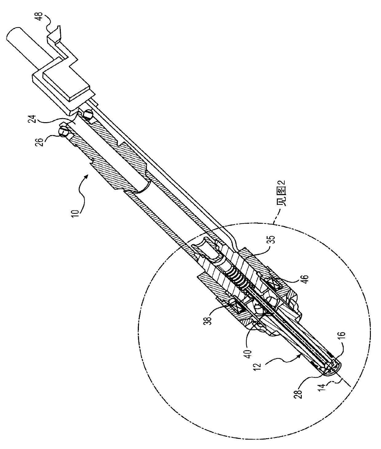
[0011] refer to figure 1 with 2 , a solenoid-actuated bipolar direct fuel injector, generally indicated at 10 , may be of the so-called top feed type, supplying fuel (eg gasoline) to an internal combustion engine (not shown). The fuel injector 10 includes a valve body, generally indicated at 12 , extending along a longitudinal axis 14 . The valve body 12 includes a valve seat 16 defining a seating surface 18 , which may have a frustoconical or concave shape, facing the interior of the valve body 12 . The seating surface 18 includes at least one fuel outlet opening 20 which is preferably centered on the longitudinal axis 14 and communicates with an inlet duct 22 for conducting pressurized fuel against the seating surface 18 into the valve body 12 . A proximal portion of the inlet tube 22 defines an inlet end 24 of the injector 10 . O-ring 26 ( figure 1 ) for sealing the inlet end 24 in the fuel rail (not shown).

[0012] A closure member (eg, spherical valve ball 28 ) with...


PUM


Abstract

A direct fuel injector (10) includes a body (12) having a passage between inlet and outlet ends. A seat (16) is at the outlet end and a closure member (28) is associated with the seat. A needle member (30) is associated with the closure member and is movable with respect to a pole piece (35) between a first, closed position and a second, open position. A spring (42) biases the needle member to the first position. An armature (32) is free-floating with respect to the needle member. An intermediate pole structure (38) is coupled with the needle member and is disposed between the pole piece and the armature and is decoupled there-from. An armature stop (40) is coupled to the needle member and is spaced from the intermediate pole structure. An electromagnetic coil (46) is associated with the pole piece, intermediate pole structure and armature. The injector reduces bounce of the needle assembly.

Description

technical field [0001] The present invention relates to fuel injectors for supplying gasoline to an engine, and more particularly to fuel injectors having an intermediate pole to increase the velocity and force generated within the injector solenoid while increasing the anti-bounce mechanism within the injector . Background technique [0002] Conventional direct injection solenoid fuel injectors have an anti-bounce mechanism to limit bounce of the armature and thus inadvertent opening of the injector. However, these conventional mechanisms make the closing of the injector often slow or the resulting magnetic force not high enough for new higher pressure applications. Another drawback of the prior art lies in the configuration of the manufactured components. These conventional direct injectors are not configured in a modular fashion, and thus cannot be constructed and tested in a modular stage. This results in scrap during manufacture and thus increases costs. [0003] Ac...

Claims


Application Information

Patent Timeline
Patent Type & Authority Applications(China)
IPC IPC(8): F02M51/06F02M61/18
CPCF02M2200/306F02M51/0671F02M51/0685F02M2200/304F02M61/188F02M2200/08Y10S239/90F02M61/1886
Inventor M.J.霍恩比
Owner VITESCO TECH USA
Why Eureka
Try Eureka