

Body protective frame
A protection frame and body technology, applied in the field of medical devices, can solve problems such as unfavorable rehabilitation, affecting blood circulation, and unsatisfactory limb warmth.
- Summary
- Abstract
- Description
- Claims
- Application Information
AI Technical Summary
Problems solved by technology
Method used
Image

Examples
Embodiment 1
[0019] Embodiment 1 The body protection frame is characterized in that it is composed of a plurality of parallel arc-shaped brackets distributed along the length direction and connected to each other. The arc-shaped brackets are foldable brackets, which can be arc-shaped brackets connected by hinges. It is a collapsible support; it can also be other various forms of collapsible supports. For example, the multiple parallel foldable arc-shaped supports distributed at intervals along the length direction are unfolded or folded through hinges. It may also be that the multiple parallel foldable arc-shaped brackets distributed at intervals along the length direction are connected through the tie rods 5, so that a stable frame body is formed therebetween. It is also possible that the said tie rods 5 are two, and the two tie rods 5 are parallel to each other, one connects the left arc support 1 of all the arc supports, and the other connects the right arc support 2 of all the arc supp...
Embodiment 2
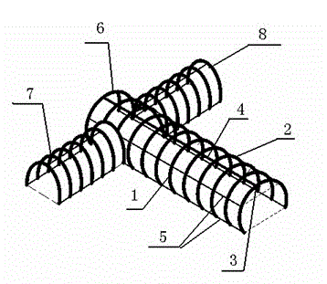
[0020] Example 2 as figure 1 As shown: this body protection frame is composed of a plurality of parallel arc-shaped brackets spaced along the length direction and connected to each other through a connecting rod 4 . Each arc-shaped bracket is made of stainless steel pipe, and each arc-shaped bracket is composed of a left arc-shaped bracket 1 and a right arc-shaped bracket 2. There is a connecting hole 3 at one end of the left arc-shaped bracket 1 and the right arc-shaped bracket 2. The rod 4 passes through the connecting hole 3 of the left arc-shaped bracket 1 and the right arc-shaped bracket 2 to connect the left arc-shaped bracket 1 and the right arc-shaped bracket 2 with the movable axis of the connecting rod 4, and the left arc-shaped bracket 1 and the right arc-shaped bracket 2 The other ends form an ellipse when combined, and the connecting rod 4 is also made of stainless steel.
[0021] There are three groups of multiple foldable stainless steel arc-shaped brackets tha...
Embodiment 3
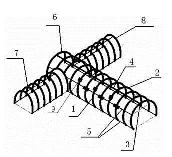
[0023] Such as figure 2 As shown, embodiment 3 has the same structure as embodiment 1 and embodiment 2, but there are permanent magnet sleeves 9 distributed and socketed on the arc support. In order to make the permanent magnet sleeves 9 not easy to damage, the permanent magnet sleeves 9 have protective sleeves. Adding the permanent magnet cover 9 can effectively promote wound healing, and reduce the degree of bleeding and exudation in different degrees on the surgical patient's limb operation or post-injury wound.
[0024] The left arc bracket 1 and the right arc bracket 2 are connected through the movable shaft of the connecting rod 4, and the connecting rod 4 has a positioning sleeve to make the positioning between the arc brackets. In addition, the two tie rods have movable positioning sleeves, which can also position the arc brackets.
[0025] The connecting rod and the two tie rods are magnetized metal rods. Can maximize the magnetic field. When the connecting rod an...
PUM
 Abstract
Description
Claims
Application Information