

Oiling device
An oil coating and oil cavity technology, which is applied to coatings, devices for coating liquid on surfaces, and motor tools, etc., can solve the problems of indeterminate amount of lubricating oil waste, high fatigue strength of personnel, and low operating efficiency, and reduce the number of personnel. The effect of investment, saving work time and reducing physical exertion
- Summary
- Abstract
- Description
- Claims
- Application Information
AI Technical Summary
Problems solved by technology
Method used
Image

Examples
Embodiment Construction
[0017] In order to make the technical means, creative features, goals and effects achieved by the present invention easy to understand, the present invention will be further described below in conjunction with specific illustrations.
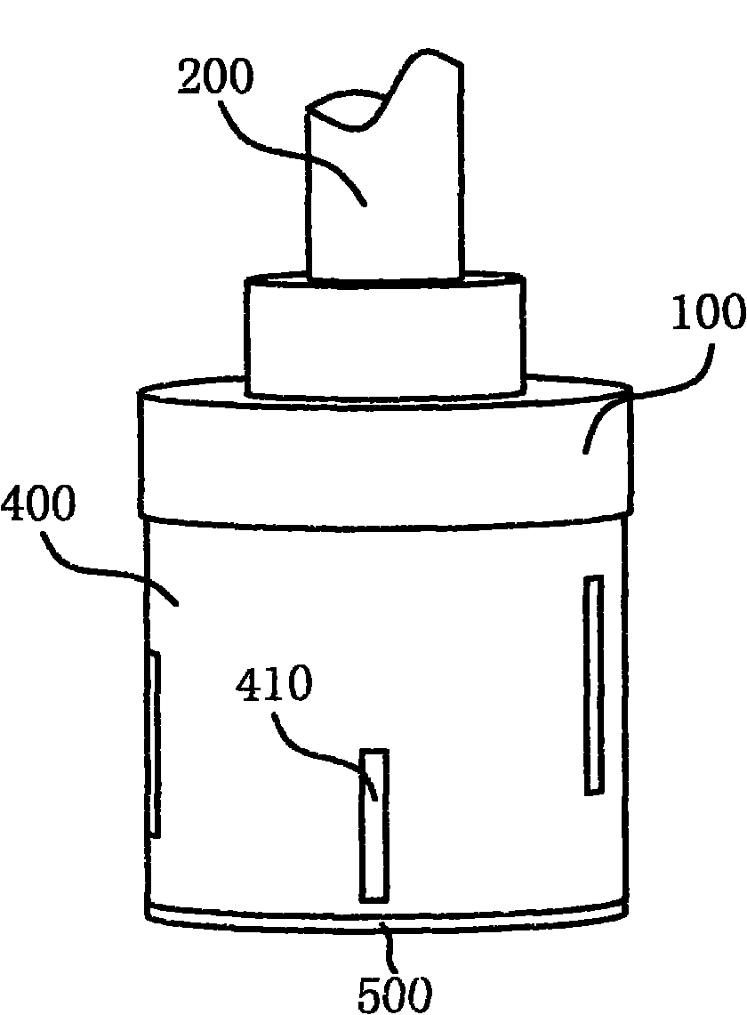
[0018] Such as figure 1 As shown, the lubricator includes a transmission shaft 200 , a connecting flange 100 , an outer cover 400 flanged to the connecting flange 100 and a lower cover plate 500 at the lower end of the outer cover 400 , and an oil retaining mechanism 410 is arranged on the outer cover 400 .
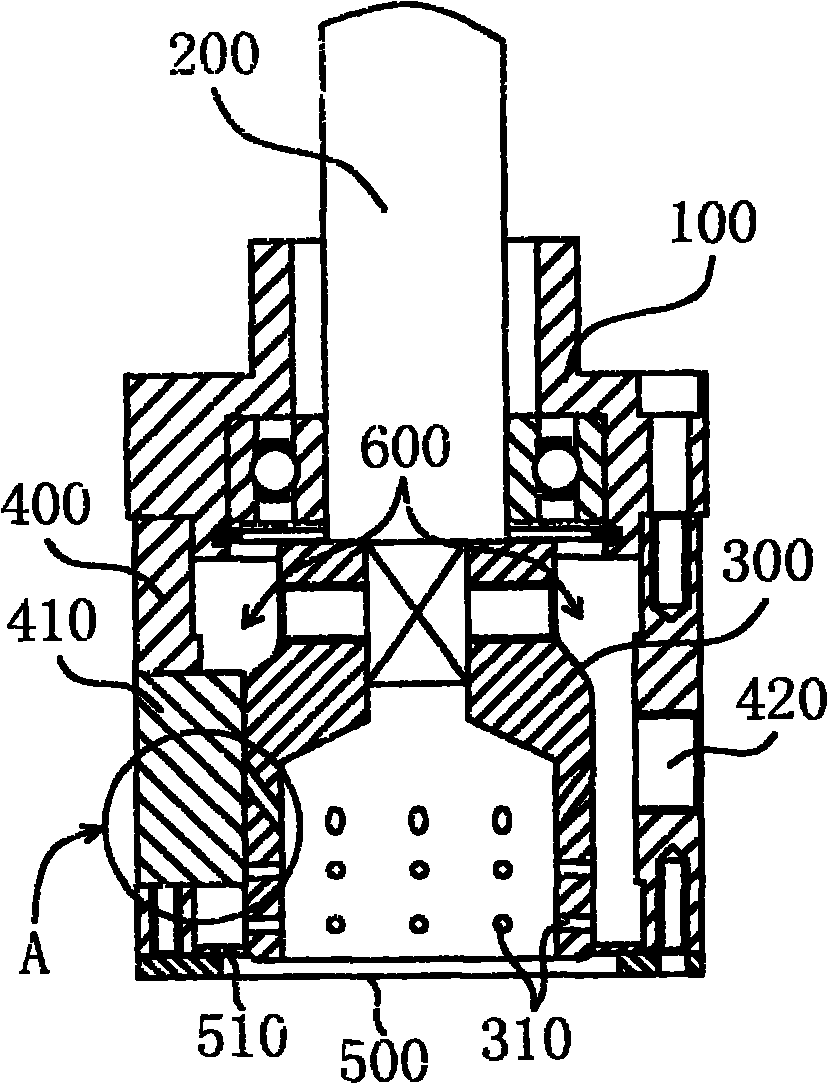
[0019] Such as figure 2 As shown, the transmission shaft 200 is installed on the shaft sleeve of the connecting flange 100 through bearings, and its lower end is connected to a sleeve 300, and several through holes 310 are arranged on the wall of the sleeve 300, and the outer wall of the sleeve 300 and the outer cover 400 An oil cavity 600 is formed between the inner walls of the sleeve 300, and the oil cavity 600 communicates with the in...
PUM
 Abstract
Description
Claims
Application Information