
Spiral tubular discharging unit for ozone generator

A technology for ozone generators and discharge units, applied in the field of ozone generators, can solve the problems of small discharge specific surface area of ​​ozone generators, large footprint of large-scale equipment, high installation and maintenance costs, and reduce equipment investment and maintenance costs. Increased ozone production and concentration, low cost effect

Active Publication Date: 2015-03-25
FUJIAN NEWLAND ENTECH CO LTD
View PDF3 Cites 0 Cited by
  • Summary
  • Abstract
  • Description
  • Claims
  • Application Information

AI Technical Summary

Problems solved by technology

But its disadvantage is that each discharge unit is a separate set of high-voltage electrodes, insulating tubes and ground electrodes, the discharge gap is large, and the discharge specific surface area of ​​the entire ozone generator is small, resulting in a decrease in the ozone production rate and making a single device The output is small, and the large-scale equipment occupies a large area; and the high-voltage electrodes, insulating pipes and ground electrodes are concentric, so the requirements for installation are also high, and the insulating pipes are prone to damage, resulting in high installation and maintenance costs. Stainless steel, glass or ceramics and other materials, so the investment cost of the entire equipment is also high, so it is necessary to overcome the above shortcomings, a large specific surface area, high ozone production rate, small footprint, low investment and maintenance costs, and easy operation Manufactured, easy-to-install discharge unit

Method used


Image

  • Spiral tubular discharging unit for ozone generator
  • Spiral tubular discharging unit for ozone generator
  • Spiral tubular discharging unit for ozone generator

Examples


Embodiment Construction

[0033] The following is attached Figure 1-3 Two embodiments of the present invention are described in detail.

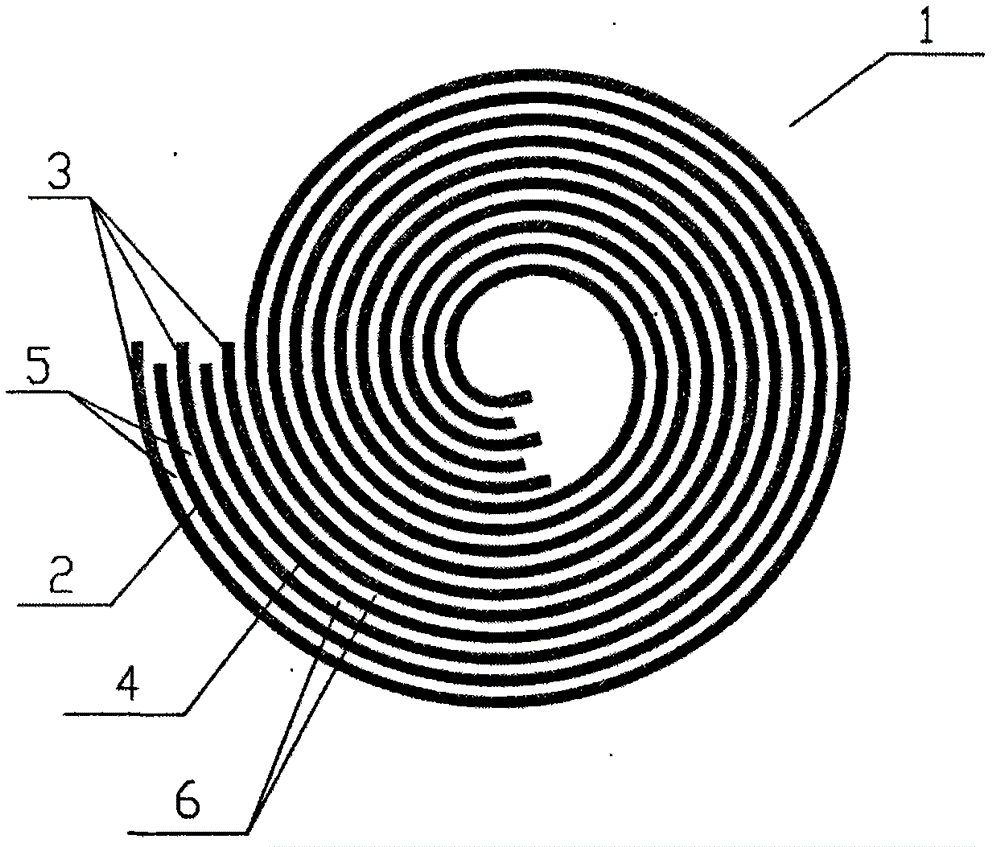
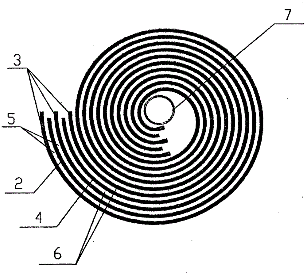
[0034] Such as figure 1 As shown, the purpose of the present invention provides a spiral tubular discharge unit 1 for an ozone generator, consisting of a group of not less than one sheet-shaped and rollable ground electrode 2, an insulating layer 3 and a high-voltage electrode 4 overlapping each other And the whole is rolled into a spiral cylinder shape along one edge thereof, the high-voltage electrode 4 and the ground electrode 2 are separated by an insulating layer 3, and one or both surfaces of the insulating layer 3 are simultaneously provided with protrusions 8. The edge of the insulating layer 3 exceeds the edge of the ground electrode 2 and the high voltage electrode 4 , and there are discharge gaps between the ground electrode 2 and the insulating layer 3 and between the insulating layer 3 and the high voltage electrode 4 . Preferably, the size of the dis...


PUM

PropertyMeasurementUnit
heightaaaaaaaaaa

Abstract

The invention provides a spiral tubular discharging unit for an ozone generator. The discharging unit is formed by interlapping a group of not less than one ground electrode, not less than one insulating layers and not less than one high-voltage electrodes and rolling all parts along an edge until a spiral cylinder is formed, wherein the ground electrodes, insulating layers and high-voltage electrodes are sheet and can be bent; the high-voltage electrodes are separated from the ground electrodes by the insulating layers; a bulge or bulges are formed on one or two surfaces of the insulating layers, on one or two surfaces of each of the ground electrodes and the high-voltage electrodes, or on one or two surfaces of each of the ground electrodes, the high-voltage electrodes and the insulating layers; edges of the insulating layers exceeds the edges of the ground electrodes and the high-voltage electrodes; and discharging gaps are respectively formed between the ground electrodes and the insulating layers as well as between the insulating layers and the high-voltage electrodes. The spiral tubular discharging unit can be applied to various ozone generators, in particular large-scale ozone generators.

Description

Technical field: [0001] The invention belongs to the field of ozone generators and relates to a discharge unit of the ozone generator. technical background: [0002] The stacked discharge unit of the existing large-scale ozone generator generally includes a concentrically installed high-voltage electrode, an insulating tube and a ground electrode, and the sequence from the inside to the outside is the high-voltage electrode, the insulating tube and the ground electrode. Generally, ceramic-coated glass tubes are used as insulating tubes, and stainless steel tubes are used as electrode materials. Dry and purified air or oxygen passes through the discharge gap between the electrodes and the insulating layer. After electrification, ozone is generated in the gap. But its disadvantage is that each discharge unit is a separate set of high-voltage electrodes, insulating tubes and ground electrodes, the discharge gap is large, and the discharge specific surface area of ​​the entire o...

Claims


Application Information

Patent Timeline
Patent Type & Authority Patents(China)
IPC IPC(8): C01B13/11
Inventor 陈健
Owner FUJIAN NEWLAND ENTECH CO LTD
Learn More