Expansion valve

A technology for expansion valves and spools, applied in mechanical equipment, fluid circulation arrangements, refrigeration components, etc., can solve problems such as increased refrigerant resistance, increased energy consumption of air conditioners, frequent impacts of spools, etc., to reduce frequent actions and simple structure , the effect of reducing flow resistance

Active Publication Date: 2013-01-16
浙江泽顺制冷科技有限公司
View PDF6 Cites 14 Cited by
  • Summary
  • Abstract
  • Description
  • Claims
  • Application Information

AI Technical Summary

Problems solved by technology

In reverse circulation, it can only flow through the orifice on the valve core, and the diameter of the valve cannot be changed, which increases unnecessary resistance when the refrigerant circulates and increases the energy consumption of the air conditioner.
And when reversed, the orifice is blocked by the movable part, and the valve core must be pushed open to flow, which causes the valve core to frequently impact under the force of the spring, reducing the service life of the valve

Method used


Image

  • Expansion valve
  • Expansion valve
  • Expansion valve

Examples


Embodiment 1

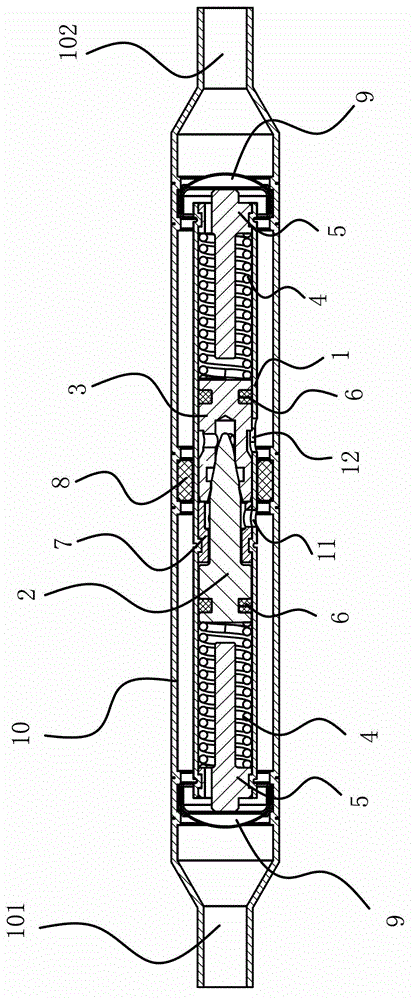
[0039] Such as figure 1 As shown, the expansion valve includes a casing 10 having an inlet port 101 and an outlet port 102. A straight cylindrical valve body 1 with an inner cavity is fixed inside the outer casing 10, and a valve body 1 is provided on the side wall to communicate with the inner cavity and the outer casing 10. The inlet 11 and the outlet 12, a spacer 8 is provided between the shell 10 and the valve body 1 to isolate the inlet 11 and the outlet 12, and the inner cavity is provided with a valve core one 2 and a valve core two 3 that can slide along the inner cavity, A retaining ring 7 is fixed in the middle of the inner cavity between the valve core one 2 and the valve core two 3, and the two ends of the inner cavity are respectively provided with spring assemblies that make the valve core one 2 and the valve core two 3 have a tendency to move toward the retaining ring 7, the valve A damping structure capable of buffering the first valve core 2 and the second val...

Embodiment 2

[0051] The structure and principle of embodiment two are basically similar to embodiment one, as Figure 6 As shown, the difference from Embodiment 1 lies in the addition of a small flow guide track structure. The structure of the small flow diversion track is that the valve core 2 3 is provided with a through hole 34 communicating with the outside of the valve body 1 and the hollow groove 33, and the through hole 34 is inlaid with a capillary. The flow rate of the through hole 34 can be changed by adding a capillary.

Embodiment 3

[0053] The structure and principle of embodiment three are basically similar to embodiment two, as Figure 7 As shown, the difference from the second embodiment lies in the structure of the small flow diversion track. The small flow diversion track structure is that the valve core one 2 is provided with a diversion groove 27 which can communicate with the hollow groove 33 and the front cylindrical hole 36 .


PUM


Abstract

The invention provides an expansion valve, belongs to the technical field of air conditioners, and solves the problem that the service life of the valve is shortened in the existing valve core of the expansion valve due to the frequent shocking of the force of a spring. The expansion valve comprises a shell provided with an inlet end and an outlet end, wherein the shell is internally provided with a valve body provided with an inner cavity which is of a straight tube shape, and the side wall of the valve body is provided with an inlet and an outlet which are communicated with the inner cavity and the shell; a distance sleeve used for obstructing the inlet and the outlet is arranged between the shell and the valve body, and the inner cavity is internally provided with a valve core I and a valve core II which can slide along the inner cavity and are matched with each other; a check ring is fixedly arranged in the middle of the inner cavity between the valve core I and the valve core II, and the two ends of the inner cavity are respectively provided with a spring assembly which can cause the valve core I and the valve core II to be provided with a moving trend to the check ring; and a damping structure is arranged between the valve core I and the valve core II and has a damping effect. Due to the existence of the damping structure, the valve core I approaches to the valve core II with a buffering process, therefore, the impulsion between the valve cores is reduced, and the service life of the expansion valve is prolonged.

Description

technical field [0001] The invention belongs to the technical field of air conditioners and relates to a mechanical automatic expansion valve for refrigeration of frequency conversion air conditioners. Background technique [0002] The expansion valve is an important part in the refrigeration system, generally installed between the condenser and the evaporator. The expansion valve can make the gas evaporated by the evaporator pressurized and liquefied into a high-temperature and high-pressure liquid refrigerant through the compressor, and throttling through its orifice to become a low-temperature and low-pressure mist liquid refrigerant, and then the refrigerant absorbs in the evaporator The heat achieves the cooling effect. The expansion valve controls the flow rate of the valve through the change of superheat at the end of the evaporator, so as to prevent the liquid impact caused by inhalation of the compressor due to insufficient utilization of the evaporator area due to...

Claims


Application Information

Patent Timeline
Patent Type & Authority Applications(China)
IPC IPC(8): F25B41/06
CPCF25B2500/12F25B41/325F25B41/38F25B41/33F25B2341/063
Inventor 金耿阮义兵
Owner 浙江泽顺制冷科技有限公司
Why Eureka
Try Eureka