
Test system for grounding grid

A test system and grounding grid technology, which is applied in the field of grounding grid test system, can solve the problems of bulky test equipment, complicated test process, and high work intensity of test personnel, and achieve the effects of small size, avoiding interference, and easy operation

Inactive Publication Date: 2013-01-16
STATE GRID ZHEJIANG NINGBO YINZHOU POWER SUPPLY LTD CO +1
View PDF5 Cites 14 Cited by
  • Summary
  • Abstract
  • Description
  • Claims
  • Application Information

AI Technical Summary

Problems solved by technology

Due to the interference of the current flowing into the ground network of the system and the interference between the test lead wires, in the prior art, the regulations require that the test current should not be less than 50A to reduce the influence of interference on the measurement results. The test equipment is bulky, the test process is complicated, and the work intensity of the test personnel is high.

Method used


Image

  • Test system for grounding grid
  • Test system for grounding grid
  • Test system for grounding grid

Examples


Embodiment Construction

[0024] The technical solutions in the embodiments of the present invention will be clearly and completely described below in conjunction with the accompanying drawings in the embodiments of the present invention. Obviously, the described embodiments are only a part of the embodiments of the present invention, rather than all the embodiments. Based on the embodiments of the present invention, all other embodiments obtained by those of ordinary skill in the art without creative work shall fall within the protection scope of the present invention.

[0025] In the prior art, the power frequency high current method is used to conduct various tests on grounding equipment. In this method, the regulations require that the test current should not be less than 50A. As a result, the test equipment is bulky and the test process is complicated. Many problems such as high work intensity.

[0026] To this end, in the embodiment of the present invention, a grounding grid test system is provided, w...


PUM


Abstract

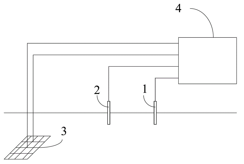
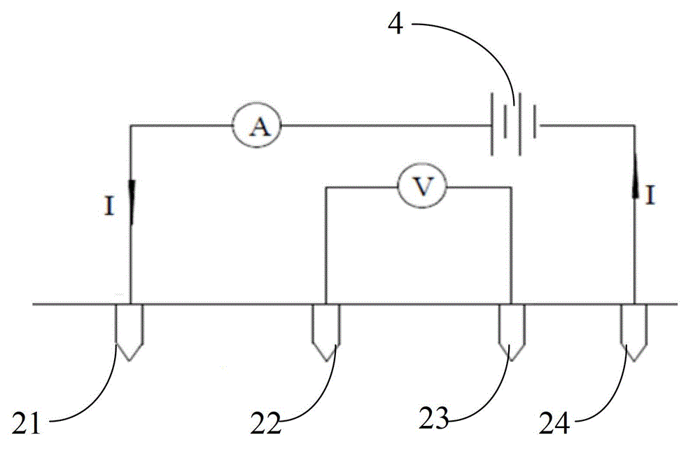
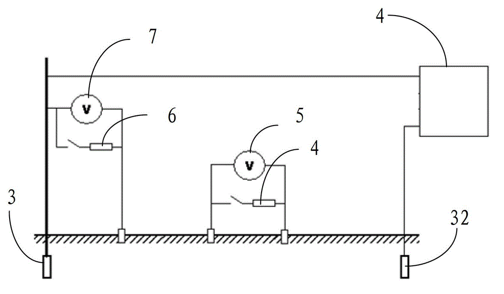
The embodiment discloses a test system for a grounding grid. The test system comprises piles, a power supply forming a set frequency difference with power frequency, human body simulation resistors, a parameter acquisition device and an arithmetic device. The piles comprise current piles and voltage piles. The parameter acquisition device is used for acquiring current values of the current piles and voltage values of the voltage piles, acquiring a distance between a first pile and a second pile and a distance and a resistance value between the second pile and a third pile, and acquiring voltage values at the two ends of each of a first human body simulation resistor and a second human body simulation resistor, wherein the current values of the current piles and the voltage values of the voltage piles are measured according to a straight-line method; and the distance between the first and second piles and the distance and the resistance value between the second and third piles are measured according to a quadrupole equal-interval method. The arithmetic device is used for calculating grounding resistance, soil resistivity, contact resistance and step resistance according to a set formula. Non-power frequency current is used for testing, so that the interference of the power frequency to the measurement current is avoided, the adoption of heavy current for measurement is not required, and the size of the measurement power supply is reduced.

Description

Technical field [0001] The invention relates to the field of electric power, and more specifically, to a grounding grid test system. Background technique [0002] In recent years, the expansion of many domestic substations has resulted in the failure of the grounding grid itself and its surrounding electrical properties. For example, when the grounding resistance is too large and a ground fault occurs, the neutral point voltage shift will increase. If the voltage of the sound phase and the neutral point is too high, it may exceed the required insulation level and cause equipment damage. Excessive grounding resistance, in addition to the excessive resistivity of the grounding grid itself, is also closely related to the resistivity of the soil around the grounding grid. In addition, when the step voltage around the grounding grid exceeds the safe voltage value, it will directly threaten the personal safety of substation operators and substation maintenance personnel. [0003] Wheth...

Claims


Application Information

Patent Timeline
Patent Type & Authority Applications(China)
IPC IPC(8): G01R31/00G01R27/20
Inventor 朱瑾王勇光卢雷任伟宏吴明刘亮泽
Owner STATE GRID ZHEJIANG NINGBO YINZHOU POWER SUPPLY LTD CO
Learn More