Non-alignment error correction method used for geomagnetic element measuring system

A measurement system and technology of geomagnetic elements, applied in the field of magnetic measurement, can solve the problems of high adjustment accuracy requirements, affecting calibration accuracy, and high operating experience requirements

Active Publication Date: 2013-01-16
NAT UNIV OF DEFENSE TECH
View PDF2 Cites 28 Cited by
  • Summary
  • Abstract
  • Description
  • Claims
  • Application Information

AI Technical Summary

Problems solved by technology

However, this method requires precise adjustment of the three-dimensional coordinate system of the optical system, and the local magnetic inclination information is needed, and the initial coordinate system of the regular hexahedral optical prism is consistent with the local north, east, and ground coordinate systems
Therefore, this method has high requirements for the precise adjustment of the initial coordinate system of the optical system and the optical prism.
[0007] 3. Using a six-dimensional DOF robot to correct misalignment errors; similarly, this method requires precise control of the attitude and is complex to operate
[0009] 5. Some practitioners package the magnetic sensor and accelerometer into an open plastic resin material regular hexahedron, place the regular hexahedron on a non-m...

Method used


Image

  • Non-alignment error correction method used for geomagnetic element measuring system
  • Non-alignment error correction method used for geomagnetic element measuring system
  • Non-alignment error correction method used for geomagnetic element measuring system

Examples


Embodiment Construction

[0043] The present invention will be further described in detail below in conjunction with the accompanying drawings and specific embodiments.

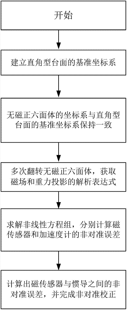
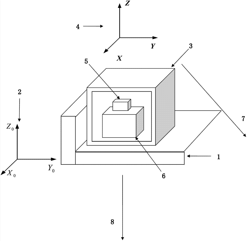
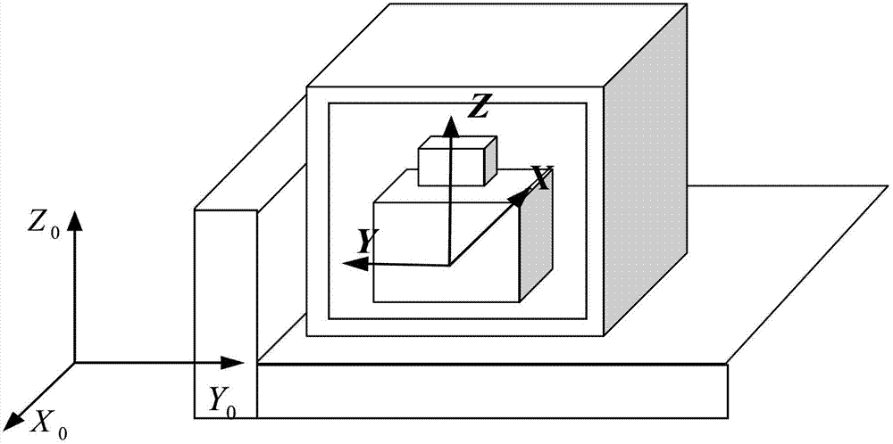
[0044] The misalignment error correction method used in the geomagnetic element measurement system of the present invention is as follows: the magnetic sensor 5 and the accelerometer 6 are packaged in a non-magnetic regular hexahedron 3, and the coordinate system relationship of the two sensors is indirectly converted to the non-magnetic regular hexahedron 3. The relationship between the regular hexahedral coordinate system 4 of the hexahedron 3; initially, the regular hexahedral coordinate system 4 of the non-magnetic regular hexahedron 3 is kept consistent with the reference coordinate system 2 of a right-angled mesa 1. Flipping the non-magnetic regular hexahedron 3, during the flipping process, since the non-magnetic regular hexahedron 3 is close to the reference coordinate system 2, the magnetic field projection of the regular hexa...


PUM


Abstract

The invention discloses a non-alignment error correction method used for a geomagnetic element measuring system, which comprises the following steps: (1) a rectangular table-board is arranged and a reference coordinate system for the rectangular table-board is established; (2) a magnetic sensor of the geomagnetic element measuring system and an accelerometer are encapsulated together in a non-magnetic regular hexahedron; two surfaces of the non-magnetic regular hexahedron are attached to two vertical surfaces of the rectangular table-board; and a regular hexahedron coordinate system is established for the non-magnetic regular hexahedron; (3) the non-magnetic regular hexahedron is turned for multiple times, and after multiple times of turning, the non-magnetic regular hexahedron is still attached to the rectangular table-board; (4) multiple sets of measurement values of the non-magnetic regular hexahedron and the accelerometer during the process of multiple times of turning are utilized, and through solving multiple non-linear equations simultaneously, the non-alignment error of the magnetic sensor and the non-alignment error of the accelerometer are calculated; (5) the non-alignment error between the magnetic sensor and an inertial navigation is indirectly calculated to correct the non-alignment error of the measurement value of the magnetic sensor. The method has the advantages of simple principle, facilitation of realization and operation, higher correction accuracy, etc.

Description

technical field [0001] The invention mainly relates to the technical field of magnetic measurement, in particular to a non-alignment error correction method for a geomagnetic element measurement system. Background technique [0002] Geomagnetic measurement sensors can be divided into two categories: total type and three-component type according to the difference of the measured. The "total type" measurement is the total strength of the geomagnetic field, which is customarily called scalar measurement; the "three-component type" measurement is the projection size of the total geomagnetic field on the three sensitive axes of the magnetic sensor. If the Euler angle relationship between the rectangular coordinate system formed by the three sensitive axes of the magnetic sensor and the geographic coordinate system is known, all seven elements of the geomagnetic field vector can be obtained through mathematical transformation: the northward component of the geomagnetic field, the ...

Claims


Application Information

Patent Timeline
IPC IPC(8): G01V13/00G01C25/00
Inventor 庞鸿锋罗诗途潘孟春张琦陈棣湘田武刚罗飞路
Owner NAT UNIV OF DEFENSE TECH
Why Eureka
Try Eureka