Directional antenna with slide tuning unit

A technology of tuning unit and directional antenna, applied in the direction of antenna, antenna parts, antenna grounding device, etc., can solve the problems of complex shape of directional antenna vibrator, difficult to process and debug, etc., achieve good electrical and mechanical performance, widen input impedance characteristics, The effect of wide bandwidth

Inactive Publication Date: 2013-01-16
深圳市三极天线技术有限公司
View PDF4 Cites 2 Cited by
  • Summary
  • Abstract
  • Description
  • Claims
  • Application Information

AI Technical Summary

Problems solved by technology

[0008] The technical problem to be solved by the present invention is to propose a directional antenna with a sliding tuning unit that is simple in structure, novel in structure, wide in operating

Method used

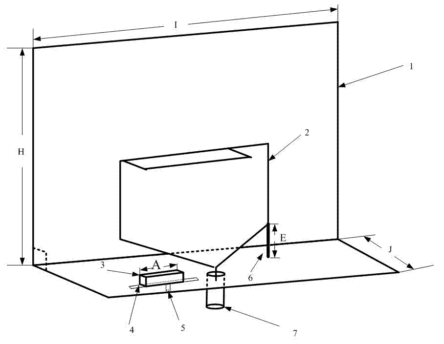
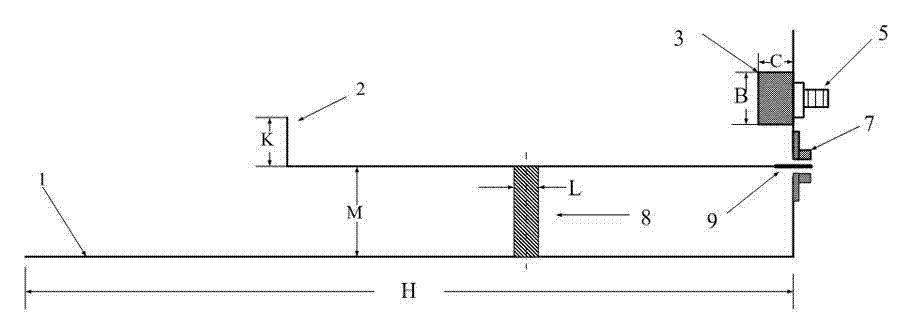
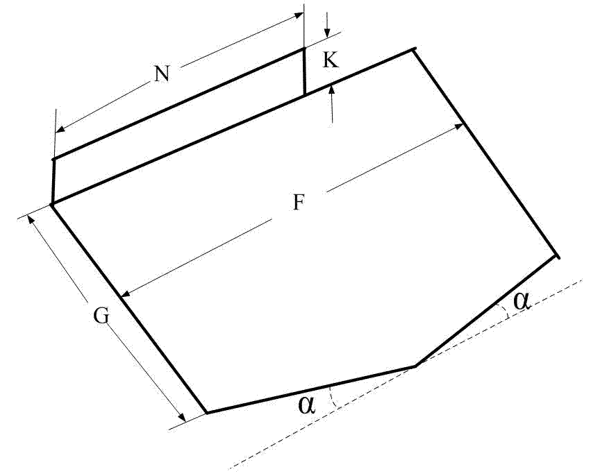

Image

  • Directional antenna with slide tuning unit
  • Directional antenna with slide tuning unit
  • Directional antenna with slide tuning unit

Examples


Embodiment Construction

[0028] Below in conjunction with accompanying drawing, technical scheme of the present invention is described in further detail:

[0029] Such as figure 1 As shown, the directional antenna with sliding tuning unit of the present invention is provided with a metal plate-shaped radiation unit 2 on a metal reflective floor 1 with folded edges; image 3 As shown, the metal plate-shaped radiation unit 2 is partially bent into a right-angled side at the top, and cut into a transition angle at the bottom, and its single end is grounded through a short metal wire 6 . A slidable tuning metal unit 3 is arranged in front of the side of the metal plate-shaped radiation unit 2; the sliding tuning unit 3 is a small cuboid metal block, and only a thin rectangular groove needs to be opened on the folded edge of the metal reflective floor, and the metal The slider is tuned to an appropriate position and fixed by screws and nuts.

[0030] combine figure 1 , figure 2 , the top bent metal pl...


PUM

PropertyMeasurementUnit
Lengthaaaaaaaaaa
Widthaaaaaaaaaa
Heightaaaaaaaaaa

Abstract

The invention discloses a directional antenna with a slide tuning unit. The directional antenna comprises a metal reflection floor (1) and a metal plate radiation unit (2) arranged on the metal reflection floor (1); the metal reflection floor (1) is a rectangular metal plate of which one end is turned into a right-angle side; one end of the metal plate radiation unit (2) is partially turned into a right-angle side, and the other end of the metal plate radiation unit (2) is provided with two symmetrical sloping sides; and on the turned bottom edge of the metal reflection floor, a sliding metal tuning unit (3) is arranged on lateral front of the metal radiation unit of the antenna, and by regulating the position of the metal tuning unit (3), an aim of widening the frequency band to tune input impedence property of the antenna is fulfilled. The antenna performance is convenient to tune, and the wide bandwidth can be effectively acquired; and the directional antenna is simple in structure, convenient to implement and low in cost and has high electrical and mechanical properties.

Description

technical field [0001] The invention relates to a directional antenna with a sliding tuning unit, and belongs to the technical field of antennas for indoor distribution systems of mobile communications. Background technique [0002] With the rapid increase of mobile users and more and more high-rise buildings in cities, the traffic density and coverage requirements are also rising. These buildings are large in scale and of good quality, and have a strong shielding effect on mobile phone signals. In the environment of low floors of large buildings, underground shopping malls, underground parking lots, etc., the mobile communication signal is weak, and the mobile phone cannot be used normally, forming a blind area and shadow area of ​​mobile communication; on the middle floor, due to the overlapping of signals from different surrounding base stations, The ping-pong effect is generated, the mobile phone is switched frequently, and even the call is dropped, which seriously affe...

Claims


Application Information

Patent Timeline
IPC IPC(8): H01Q1/00H01Q1/36H01Q1/48H01Q1/50
Inventor 程勇吕文俊朱洪波
Owner 深圳市三极天线技术有限公司
Why Eureka
Try Eureka