Phase-locked loop system and implementation method for same

A phase loop system, phase-locked loop technology, applied in the field of phase-locked loop system, can solve the problem that the phase noise cannot be suppressed at the same time

Inactive Publication Date: 2013-01-16
IPGOAL MICROELECTRONICS (SICHUAN) CO LTD
View PDF4 Cites 4 Cited by
  • Summary
  • Abstract
  • Description
  • Claims
  • Application Information

AI Technical Summary

Problems solved by technology

[0003] The problem existing in the PLL system structure in the prior art is that the noise of the input clock Fin and the phase noise of the voltage-controlled oscillator VCO cannot be suppressed at the same time. To suppress the noise of the input clock Fin, the loop bandwidth Wc<(1 / 10)Fin; to suppress the phase noise of the voltage-controlled oscillator VCO, the loop bandwidth Wc must be as large as possible. Obviously, the design of the loop bandwidth is usually difficult to simultaneously reduce the noise of the input clock Fin and the voltage-controlled oscillator VCO The phase noise is well suppressed

Method used


Image

  • Phase-locked loop system and implementation method for same
  • Phase-locked loop system and implementation method for same
  • Phase-locked loop system and implementation method for same

Examples


Embodiment Construction

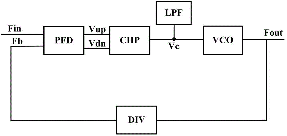
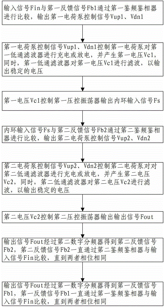
[0025] see figure 2A preferred embodiment of the phase-locked loop system of the present invention includes an input terminal, a first phase frequency detector PFD1 connected to the input terminal, and a first electric charge connected to the first phase frequency detector PFD1. pump CHP1, a first low-pass filter LPF1 connected to the first charge pump CHP1, a first voltage-controlled oscillator VCO1 connected to the first low-pass filter LPF1 and the first charge pump CHP1, and a first voltage-controlled oscillator VCO1 connected to the first charge pump CHP1 A second frequency and phase detector PFD2 connected to the first voltage-controlled oscillator VCO1, a second charge pump CHP2 connected to the second frequency and phase detector PFD2, and a second charge pump CHP2 connected to the second charge pump CHP2 The second low-pass filter LPF2, a second voltage-controlled oscillator VCO2 connected to the second low-pass filter LPF2 and the second charge pump CHP2, an output ...


PUM


Abstract

The invention discloses a phase-locked loop system, which comprises an input end, an output end, a first phase frequency detector, a first charge pump connected with the first phase frequency detector, a first low-pass filter connected with the first charge pump, a first voltage-controlled oscillator connected with the first charge pump and the first low-pass filter, a second phase frequency detector connected with the first voltage-controlled oscillator, a second charge pump connected with the second phase frequency detector, a second low-pass filter connected with the second charge pump, a second voltage-controlled oscillator connected with the second charge pump and the second low-pass filter, a first digital frequency divider connected between the first phase frequency detector and the second voltage-controlled oscillator, and a second digital frequency divider connected between the second phase frequency detector and the second voltage-controlled oscillator. The invention also discloses a working method of the phase-locked loop system. Input noise and the phase noise of the second voltage-controlled oscillator can be simultaneously suppressed, so that the noise of the phase-locked loop system is greatly reduced.

Description

technical field [0001] The invention relates to a phase-locked loop system, in particular to a phase-locked loop system capable of reducing the noise of the phase-locked loop and a method for realizing the phase-locked loop system. Background technique [0002] see figure 1 , figure 1 It is a system structure diagram of a phase-locked loop in the prior art. The phase-locked loop in the prior art is composed of a phase-frequency detector PFD, a charge pump CHP, a low-pass filter LPF, a voltage-controlled oscillator VCO and a digital frequency divider DIV Composition, wherein, the phase frequency detector PFD is used to compare the phase difference between the input clock Fin and the feedback clock Fb, and generate the charge pump control signal Vup, Vdn to control the charge pump CHP; the charge pump CHP is controlled by the charge pump control signal Vup , Vdn control, charge or discharge the voltage terminal Vc; the low-pass filter LPF is used to filter out high-frequency...

Claims


Application Information

Patent Timeline
Patent Type & Authority Applications(China)
IPC IPC(8): H03L7/085H03L7/099
CPCH03L7/07H03L7/235
Inventor 范方平
Owner IPGOAL MICROELECTRONICS (SICHUAN) CO LTD
Why Eureka
Try Eureka