Full anechoic darkroom
A technology of full anechoic chamber and test room, which is applied in the field of full anechoic chamber, can solve the problems of adjustment errors, time-consuming, inaccurate test readings, etc., and achieve the effect of avoiding errors
- Summary
- Abstract
- Description
- Claims
- Application Information
AI Technical Summary
Problems solved by technology
Method used
Image

Examples
Embodiment Construction
[0042] Embodiments of the present invention will be clearly explained below with the drawings and detailed description, and the same numbers in the drawings represent the same or similar components. On the other hand, well-known components and steps have not been described in the embodiments in order not to limit the invention unnecessarily.
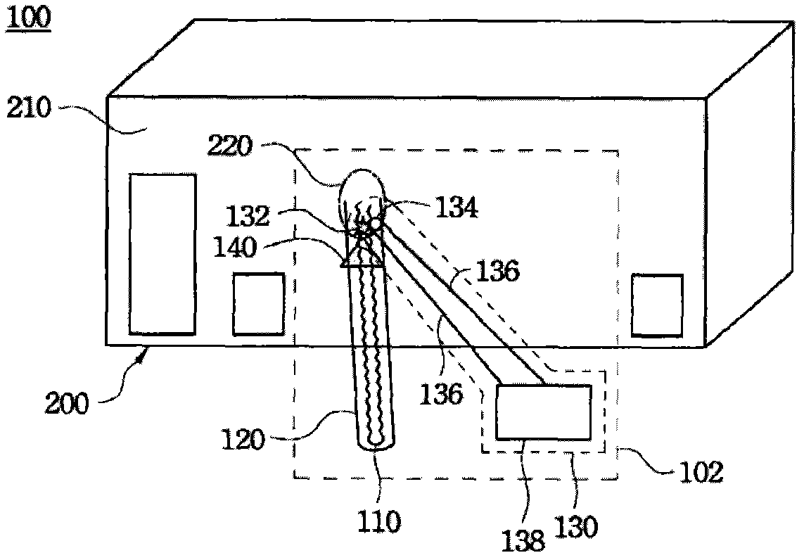
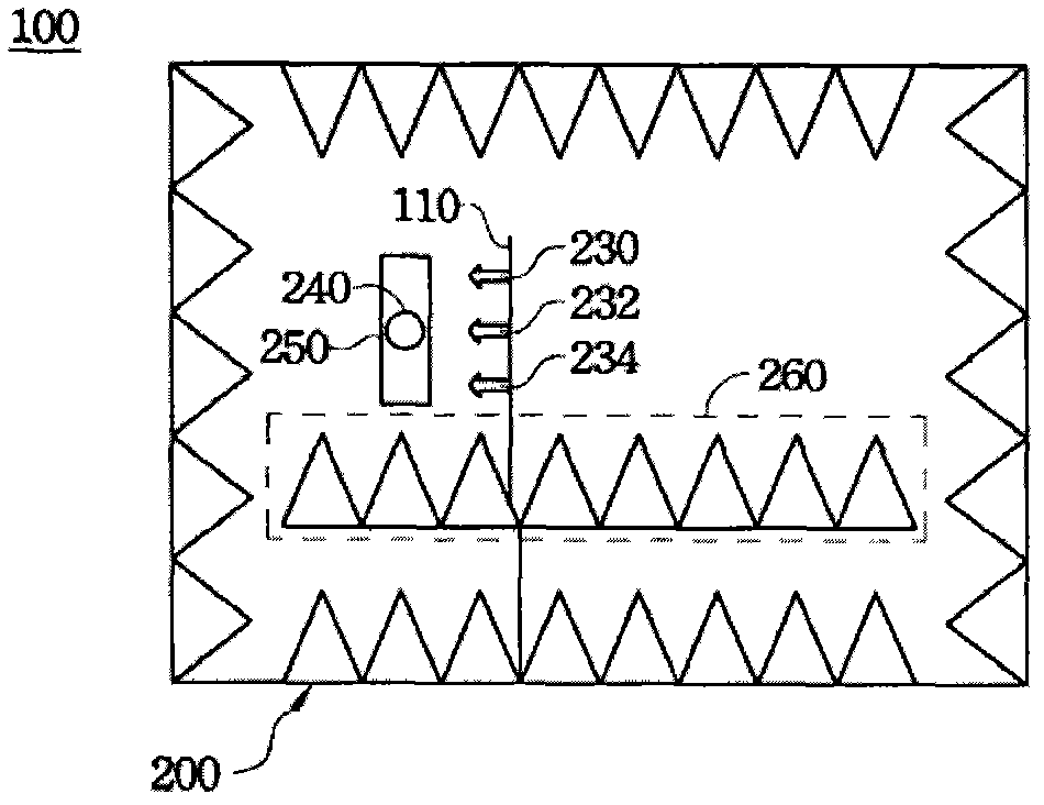
[0043] Please also refer to Figure 1A and Figure 1B , Figure 1A It is an external front view of a fully anechoic chamber 100 according to an embodiment of the present invention, Figure 1B It is an internal plan view of a fully anechoic chamber 100 according to an embodiment of the present invention.
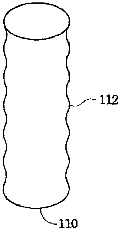
[0044] The full anechoic chamber 100 includes a test room 200 , a test turntable 250 , and an antenna stand device 102 . The test chamber 200 has an outer wall 210 with a hole 220 outside the test chamber 200 . The test turntable 250 is set in the test room 200 . The antenna stand device 102 includes an antenna stand 110 , a pipe 12...
PUM
 Abstract
Description
Claims
Application Information
 - Generate Ideas
- Intellectual Property
- Life Sciences
- Materials
- Tech Scout
- Unparalleled Data Quality
- Higher Quality Content
- 60% Fewer Hallucinations
Browse by: Latest US Patents, China's latest patents, Technical Efficacy Thesaurus, Application Domain, Technology Topic, Popular Technical Reports.
© 2025 PatSnap. All rights reserved.Legal|Privacy policy|Modern Slavery Act Transparency Statement|Sitemap|About US| Contact US: help@patsnap.com