Supercharge Your Innovation With Domain-Expert AI Agents!

A method and device for allocating IP addresses in a multi-NVR monitoring network

An IP address and monitoring network technology, applied in the field of IP address allocation of multiple NVR monitoring networks, can solve problems such as the normal operation of monitoring services, and achieve the effect of avoiding confusion and convenient use.

Active Publication Date: 2016-09-14
ZHEJIANG UNIVIEW TECH CO LTD
View PDF4 Cites 0 Cited by
  • Summary
  • Abstract
  • Description
  • Claims
  • Application Information

AI Technical Summary

Problems solved by technology

When the monitoring front-end equipment on the same layer 2 network sends a DHCP broadcast message requesting an IP address, multiple NVRs with the same address pool and the DHCP server function will cause multiple monitoring front-end equipment to be assigned the same address. It will inevitably bring troubles to the normal operation of the monitoring business

Method used


Image

  • A method and device for allocating IP addresses in a multi-NVR monitoring network
  • A method and device for allocating IP addresses in a multi-NVR monitoring network

Examples


Embodiment Construction

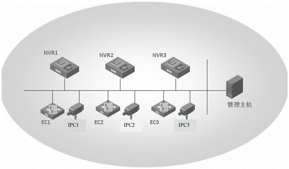
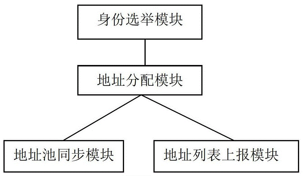
[0015] The specific embodiments of the present invention will be described below in conjunction with the accompanying drawings. Such as figure 1 An example of an IP surveillance network diagram, which includes multiple surveillance front-end devices (such as IPC and EC) and multiple network video recorders NVR (multiple NVRs include two or more than two NVRs). The monitoring front-end equipment and NVR are located in the same layer 2 network. Each NVR is a device with exactly the same function and has the same private network IP address pool. This private network IP address pool is configured before the NVR leaves the factory and is used to allocate to Front-end equipment. The device for assigning IP addresses applied to the NVR includes: an identity election module, an address assignment module, an address pool synchronization module and an address list reporting module.

[0016] Step 101, after the NVR goes online, it sends an election message to determine its primary and ...


PUM


Abstract

The invention provides a method for distributing an internet protocol (IP) address to a multi-network video recorder (NVR) by a monitoring network. The monitoring network is provided with a monitor front terminal device located at the same one second-layered network along with a plurality of network video recorders. The method comprises the following steps: after on line, a voting message is sent to determine own identification by the NVR; if the NVR is determined to be a major NVR, the NVR selects one IP address from an own address pond and distribute the IP address to the monitor front terminal device after the monitor front terminal device asks for a dynamic host configuration protocol (DHCP) broadcast message of the IP address, select one NVR as the NVR to manage the monitor front terminal device according to a load sharing principle, and inform the monitor front terminal device of the IP address of the NVR in order to register the NVR; if is the NVR is the secondary NVR, the NVR is not treated after receiving the broadcast message of the IP address asked by the monitor front terminal device. With the adoption of the method for distributing the IP address to the NVR by the monitoring network, the IP address at the same one two-layered network is distributed by the major NVR, thereby the chaos caused by performing the address distribution on the NVR with the same address pond in the second-layered network is avoided.

Description

technical field [0001] The invention relates to video monitoring, in particular to a method and device for allocating IP addresses in a multi-NVR monitoring network. Background technique [0002] IP is the abbreviation of Internet Protocol (Internet Protocol), which is the most commonly used protocol for communicating through computer networks and the Internet. IP video surveillance system (also known as network video surveillance system) can digitize video information and transmit it through wired or wireless IP network. This enables functions such as real-time monitoring and video recording to be extended to all places with network connections, and also enables such systems to be easily and seamlessly integrated with other security systems (such as access control systems, etc.). Formally based on the above characteristics, at present, the IP video surveillance system is developing towards the direction of "unified deployment + data sharing" IP surveillance network. [00...

Claims


Application Information

Patent Timeline
Patent Type & Authority Patents(China)
IPC IPC(8): H04L29/12H04N7/18
Inventor 周迪余剑声
Owner ZHEJIANG UNIVIEW TECH CO LTD
Features
  • R&D
  • Intellectual Property
  • Life Sciences
  • Materials
  • Tech Scout
  • Unparalleled Data Quality
  • Higher Quality Content
  • 60% Fewer Hallucinations
Learn More