Image pickup apparatus and image pickup device

一种摄像装置、摄像元件的技术,应用在电气元件、图像通信、彩色电视的零部件等方向,能够解决图像信号缺失、AF精度劣化、摄像图像画质劣化等问题

Active Publication Date: 2013-01-16
OLYMPUS CORP
View PDF4 Cites 20 Cited by
  • Summary
  • Abstract
  • Description
  • Claims
  • Application Information

AI Technical Summary

Problems solved by technology

[0003] However, there is a disadvantage that in order to improve the autofocus performance, it is necessary to arrange a relatively large number of AF pixels in the imaging element, and the image quality of the captured image deteriorates due to the lack of image signals in the AF pixel portion.
For example, when an interchangeable lens with a different pupil position is used, or when a zoom lens with a shifted pupil position is used, there is a problem that AF accuracy deteriorates.
[0011] In addition, in the proposal of Document 2, the reduction in the amount of light caused by the so-called shading caused by the inclination of the angle when the light from outside the optical axis of the photographing lens enters the imaging element is not considered.

Method used


Image

  • Image pickup apparatus and image pickup device
  • Image pickup apparatus and image pickup device
  • Image pickup apparatus and image pickup device

Examples


no. 1 Embodiment approach )

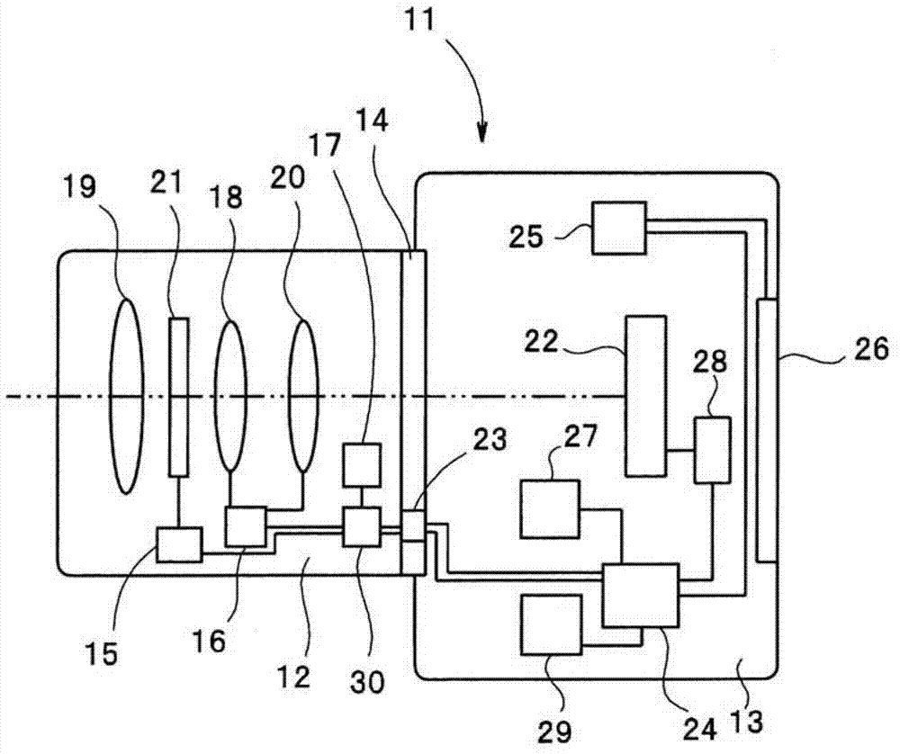
[0052] figure 1 It is a block diagram showing a camera including the imaging device according to the first embodiment of the present invention.

[0053] exist figure 1 Among them, a digital camera 11 is composed of an interchangeable lens 12 and a camera body 13 , and the interchangeable lens 12 is attached to the camera body 13 through a fixing portion 14 .

[0054] The interchangeable lens 12 includes a lens control unit 30 , a lens driving unit 16 , an aperture driving unit 15 , a zoom lens 18 , a fixed lens 19 , a focusing lens 20 , and an aperture 21 . The lens control unit 30 is composed of peripheral components such as a microcomputer and a memory, and performs drive control of the focusing lens 20 and the aperture 21, state detection of the aperture 21, the zoom lens 18, and the focusing lens 20, and control of the body control unit 24. Sending of lens information and receiving of camera information, etc.

[0055] The diaphragm drive unit 15 controls the aperture di...

no. 2 Embodiment approach )

[0117] Figure 12 It is a block diagram showing an example of a specific configuration of a fuselage control unit employed in the second embodiment. exist Figure 12 in, right with Figure 10 The same structural elements are marked with the same reference numerals and descriptions are omitted. also, Figure 13 and Figure 14 These are explanatory diagrams for explaining the information stored in the received light amount correction memories 17 and 27, respectively.

[0118] In the first embodiment, an example is shown in which the body control unit 24 uses the measured values ​​to obtain the received light amount correction coefficient α, thereby creating a table and storing it in the received light amount correction memory 27 . On the other hand, the present embodiment is different from the first embodiment in that the body control unit 71 is used to obtain the light-receiving amount correction coefficient α by arithmetic processing.

[0119] In the present embodiment, ...

no. 3 Embodiment approach )

[0134] Figure 16 It is a block diagram showing an imaging device according to a third embodiment of the present invention.

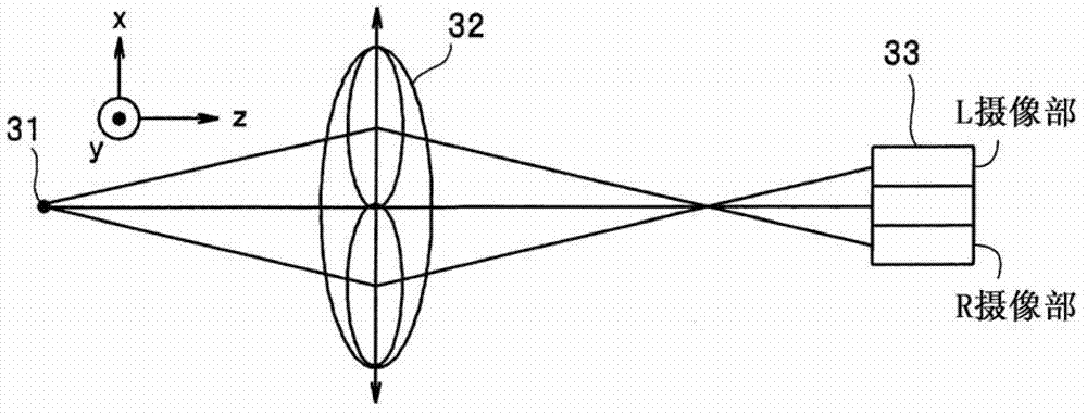
[0135] First, refer to Figure 17 to Figure 26 , the imaging element and the correction method of the image signal used in this embodiment will be described. Figure 17 It is an explanatory diagram showing the configuration of pixels in the vicinity of the optical axis of the photographing lens among the pixels constituting the imaging element.

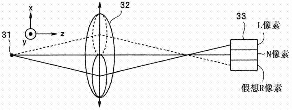
[0136] The photographic lens of the imaging device forms an optical image incident on the imaging device from the subject through each optical path, on the light receiving surface of the imaging element. As described above, by adopting the pupil division phase difference method, automatic focusing can be realized.

[0137] exist Figure 17 An example in which the pixels 151 and 152 are R pixels and L pixels are shown in . Each pixel including the pixels 151 and 152 is sequentially arranged with a microlens...


PUM


Abstract

An image pickup apparatus includes: an image pickup device that includes a pixel used for focus detection, a plurality of the pixels being arranged in a matrix; a correction memory that stores correction information used for correcting a difference in amounts of received light that depend on pixel positions of the pixels used for focus detection; a correcting section that reads the correction information to correct a pixel value of the pixel used for focus detection; and a focus detecting section that detects a focal point by using the pixel value corrected by the correcting section. Focus accuracy is increased by correcting the pixel value for an AF pixel depending on the pixel position.

Description

technical field [0001] The present invention relates to an imaging device and an imaging element with an autofocus function. Background technique [0002] In recent years, many portable devices (imaging devices) with a photography function, such as digital cameras, have an autofocus function. Some of these imaging devices use an imaging element that incorporates pixels for focus detection (hereinafter referred to as AF pixels) in addition to imaging pixels (ordinary pixels) used for image formation, and uses the pupil division phase difference method. auto focus. In this method, the pupil needs to be divided in the left and right directions, and an AF pixel having an imaging unit for receiving light beams transmitted from each of the left and right pupils needs to be configured in the imaging device. High-speed autofocus can be performed by generating and focusing an AF signal for focusing by performing calculations on image signals based on these various AF pixels (herein...

Claims


Application Information

Patent Timeline
Patent Type & Authority Applications(China)
IPC IPC(8): H04N5/225H04N5/232H04N5/335
CPCH04N5/225H04N5/3696H04N5/232H04N5/23212H04N5/335H04N23/672H04N25/704H04N25/134
Inventor 松尾圭悟后藤尚志市川良一大久保龙飞高濑弘高桥利夫村上大地
Owner OLYMPUS CORP
Why Eureka
Try Eureka