Valve unit for a coating system

A valve unit, paint technology, applied in electrostatic spraying device, thin material processing, friction discharge spraying, etc., can solve problems such as unsatisfactory material resistance

Active Publication Date: 2013-01-16
DUERR SYST GMBH
View PDF8 Cites 2 Cited by
  • Summary
  • Abstract
  • Description
  • Claims
  • Application Information

AI Technical Summary

Problems solved by technology

[0003] A disadvantage of this conventional design is that the plastic of the housing has only an unsatisfactory material resistance to the paints or rinsing agents used, since the paint or rinsing agents can attack the plastic
[0004] Another disadvantage of the previously described conventio

Method used


Image

  • Valve unit for a coating system
  • Valve unit for a coating system
  • Valve unit for a coating system

Examples


Embodiment Construction

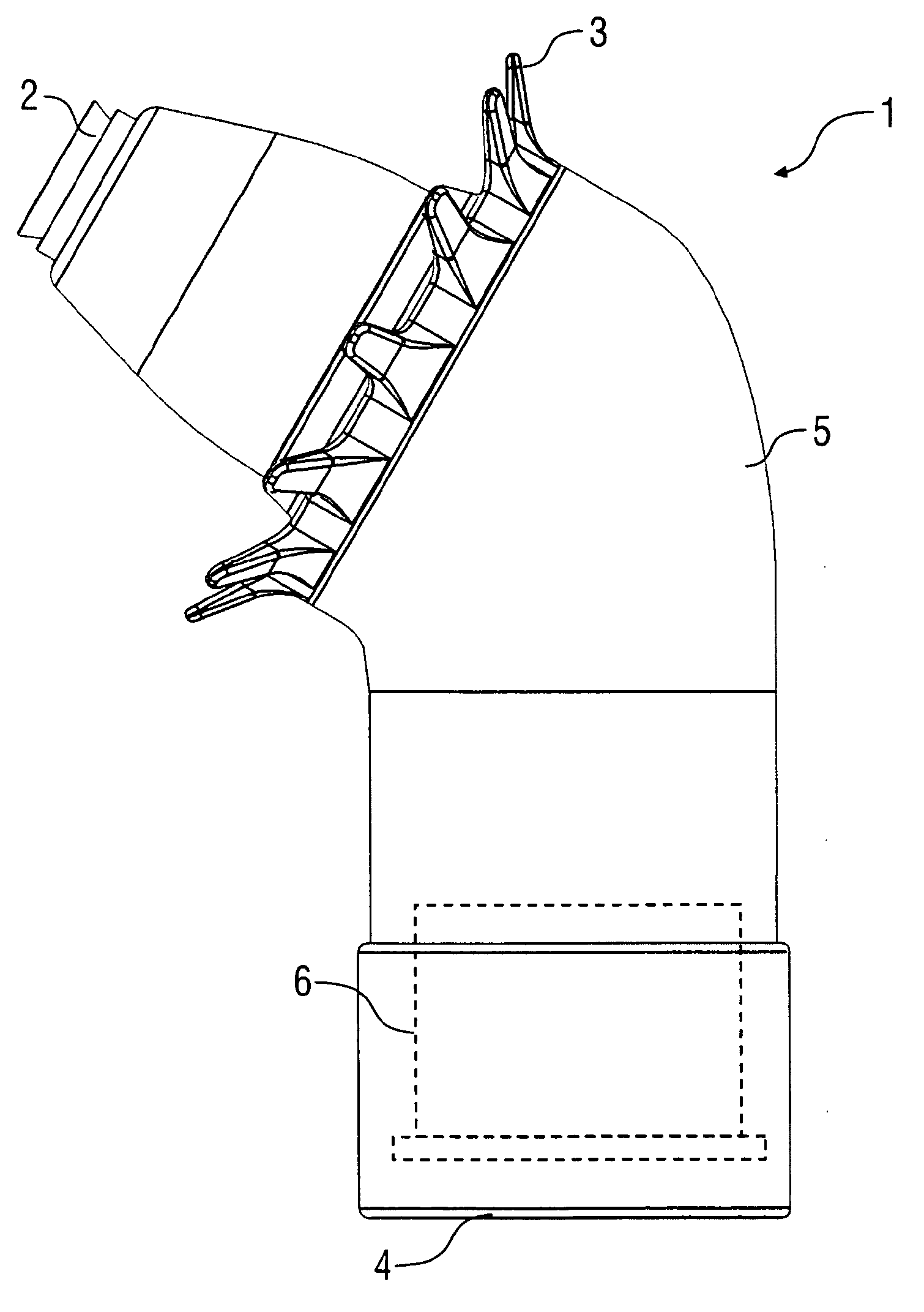
[0039] figure 1 A side view of a rotary atomizer 1 according to the invention is shown, which can be used, for example, for painting motor vehicle body parts. The rotary atomizer 1 has a rotary bell cup 2 as injection element, which is driven by a turbine.

[0040] In addition, the rotary atomizer 1 has an outer charging ring 3 in order to electrostatically charge the sprayed application agent so that the application agent deposits better on electrically grounded components.

[0041] As is known from the prior art, the rotary atomizer 1 can be fixed on a connecting flange 4 on the arm shaft of a multi-axis painting robot.

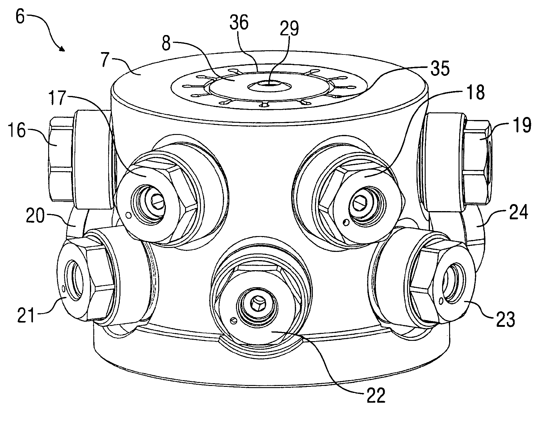
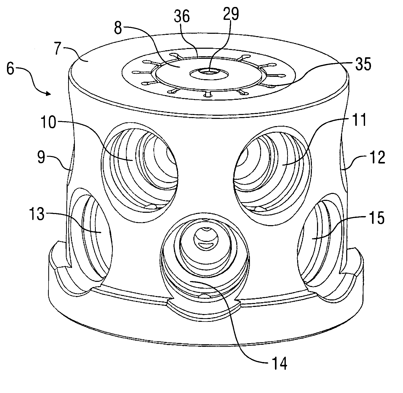
[0042] Furthermore, the rotary atomizer 1 has a housing 5 in which a valve unit 6 according to the invention is accommodated, which is used as an integrated color changer (ICC) and whose cf. Figures 2 to 5 Explained later.

[0043] The valve unit 6 has a substantially cylindrical housing comprising a cylindrical casing 7 made of plastic (eg POM: polyoxy...


PUM


Abstract

The invention relates to a valve unit (6) for a coating system, in particular as an integrated colour changer or two-component mixer in a rotary sprayer (1), having a housing (7, 8) and at least one valve receptacle (15) which is arranged in the housing (7, 8) and serves to receive a valve (21). It is proposed that the housing (7, 8) has at least one first housing part (8) and one second housing part (7), wherein the first housing part (8) is composed of a different material than the second housing part (7).

Description

technical field [0001] The invention relates to a valve unit for an application system, in particular as an integrated color changer or two-component mixer in a rotary atomizer. Background technique [0002] A rotary atomizer with an integrated color changer is known from WO 2007 / 131636 A1, in which the color changer is structurally integrated into the housing of the rotary atomizer. Furthermore, an annular structure for a color changer of this type is known from patent publication WO 2008 / 071273 A2, in which the color changer is formed by a valve unit accommodated in a housing. The known valve unit basically comprises a central applicator channel into which a plurality of applicator supply lines lead, with the aid of radially extending needle valves controlling flow from the individual applicator supply lines to the central Supply of applicator channels. The housing of the valve unit is usually made of plastic (eg POM: polyoxymethylene), wherein the valve receptacle, valv...

Claims


Application Information

Patent Timeline
IPC IPC(8): B05B12/14B05B5/04B05B5/047
CPCB05B5/04B05B12/149B05B5/047B05B12/1409Y10T137/6851
Inventor B·塞茨
Owner DUERR SYST GMBH
Why Eureka
Try Eureka