Circuit and method for operating a lighting unit and a luminaire having a circuit of this kind

A light-emitting unit and circuit technology, applied in electroluminescent light sources, light sources, electric light sources, etc., can solve problems such as reducing circuit efficiency and achieve the effect of ensuring brightness

Inactive Publication Date: 2013-01-16
OSRAM GMBH
View PDF6 Cites 0 Cited by
  • Summary
  • Abstract
  • Description
  • Claims
  • Application Information

AI Technical Summary

Problems solved by technology

This reduces the efficiency of the circuit

Method used


Image

  • Circuit and method for operating a lighting unit and a luminaire having a circuit of this kind

Examples


Embodiment Construction

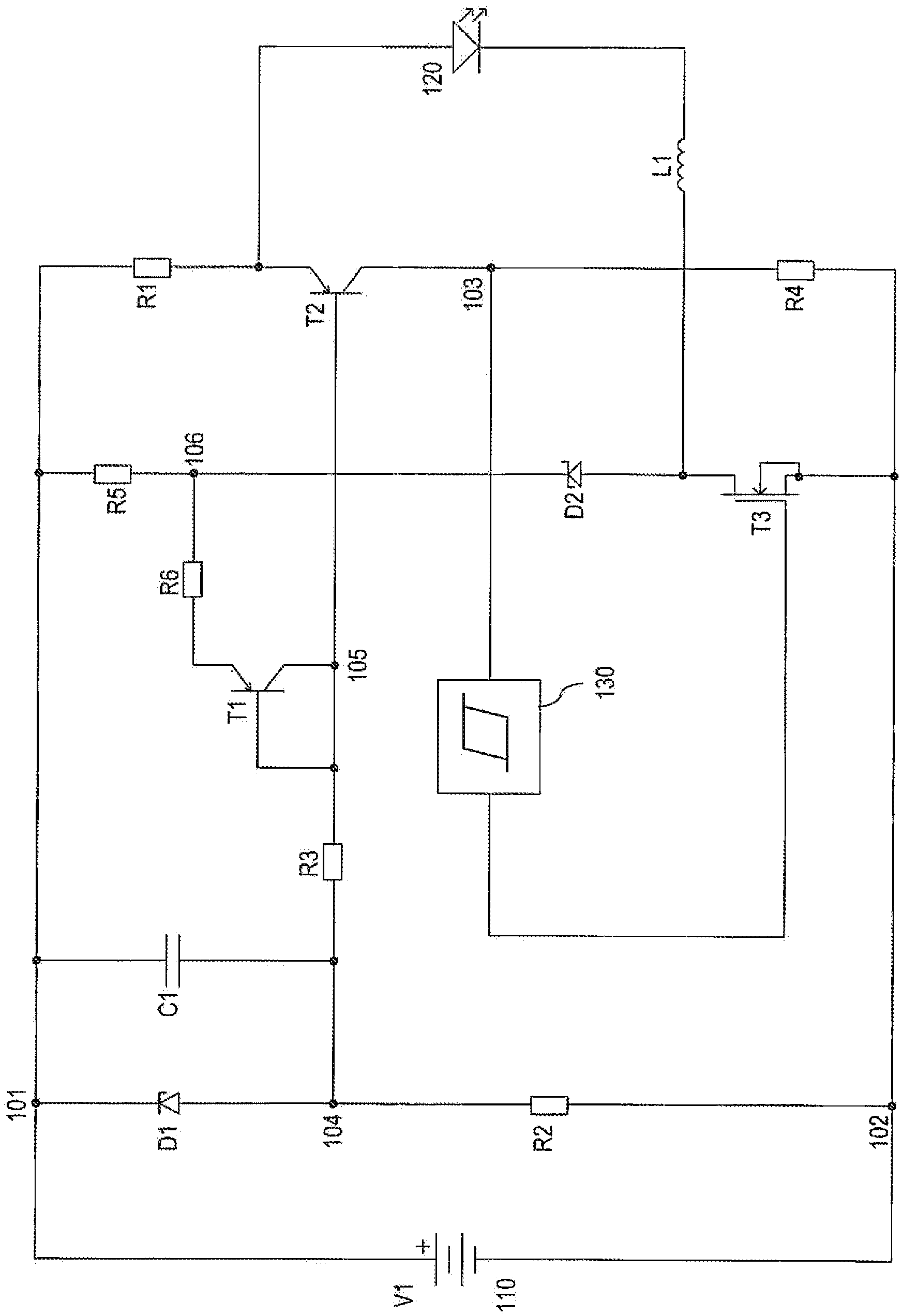
[0037] figure 1 A circuit is shown for operating at least one semiconductor light-emitting element 120 by means of a power source, for example a battery 110 supplying a supply voltage V1.

[0038] The positive terminal of battery 110 is connected to node 101 , and the negative terminal of battery 110 is connected to node 102 . The cathode of diode D1 is connected to node 101 , and the anode of diode D1 is connected to node 104 . A resistor R2 is arranged between nodes 104 and 102 . A capacitor C1 is arranged in parallel with the diode D1. Node 104 is connected to node 105 via resistor R3. The base and collector of pnp transistor T1 and the base of pnp transistor T2 are connected to node 105 . The emitter of transistor T1 is connected to node 106 via resistor R6. A resistor R5 is arranged between node 101 and node 106 . The cathode of diode D2 is connected to node 106 and the anode of diode D2 is connected to the drain terminal of n-channel Mosfet T3. The source terminal...


PUM


Abstract

The invention proposes a circuit for actuating a lighting unit (120), comprising a current mirror (T1, T2) which can be biased by means of a reference voltage source (D1); comprising a hysteresis circuit (130) which is connected to the output of the current mirror (T1, T2); comprising a step-down converter (T3, D2, L1) with an electronic switch (T3), wherein the electronic switch (T3) is connected to the output of the hysteresis circuit (130); wherein the lighting unit (120) can be actuated by means of the step-down converter (T3). A method for operating the circuit and a luminaire having a circuit of this kind are also proposed.

Description

technical field [0001] The present invention relates to circuits and methods for operating lighting units and luminaires with such circuits. Background technique [0002] Semiconductor light-emitting elements, especially light-emitting diodes (LEDs), are also increasingly used in general lighting. In order to operate such luminous elements, a simple, cost-effective and efficient power supply circuit is required. [0003] WO 2009 / 089912 presents a buck converter (Tiefsetzer) or step-down converter (Tiefsetzsteller) operating in the so-called "Continuous" mode, i.e. the main energy storage element of the converter (inductance) is not completely demagnetized during each switching cycle. The current flowing through the load (light-emitting diode) also varies between a maximum and minimum value greater than zero without additional energy storage (capacitor). The disadvantage of this solution is that the voltage will drop by a total of about 0.6V across the two shunt resistors ...

Claims


Application Information

Patent Timeline
Patent Type & Authority Applications(China)
IPC IPC(8): H05B33/08H05B44/00
CPCH05B33/0815H05B45/375H05B45/32
Inventor 贝恩德·鲁道夫
Owner OSRAM GMBH
Why Eureka
Try Eureka