Running control loop and hydraulic excavator

A technology for walking control and oil circuit control, applied in the direction of earth mover/shovel, construction, etc., can solve problems such as easy deviation, and achieve the effect of reducing labor intensity, simple solution, and improving operation efficiency.

Inactive Publication Date: 2013-01-23
SANY HEAVY MACHINERY
View PDF5 Cites 7 Cited by
  • Summary
  • Abstract
  • Description
  • Claims
  • Application Information

AI Technical Summary

Problems solved by technology

[0007] In view of this, the present invention proposes a control circuit and a hydraulic excavator to solve the problem that the hydraulic excavator is easy to deviate when it is advancing or retreating at the same time, so as to improve the working efficiency and reduce the labor intensity

Method used


Image

  • Running control loop and hydraulic excavator
  • Running control loop and hydraulic excavator

Examples


Embodiment Construction

[0039] It should be noted that, in the case of no conflict, the embodiments of the present invention and the features in the embodiments can be combined with each other. The present invention will be described in detail below with reference to the accompanying drawings and examples.

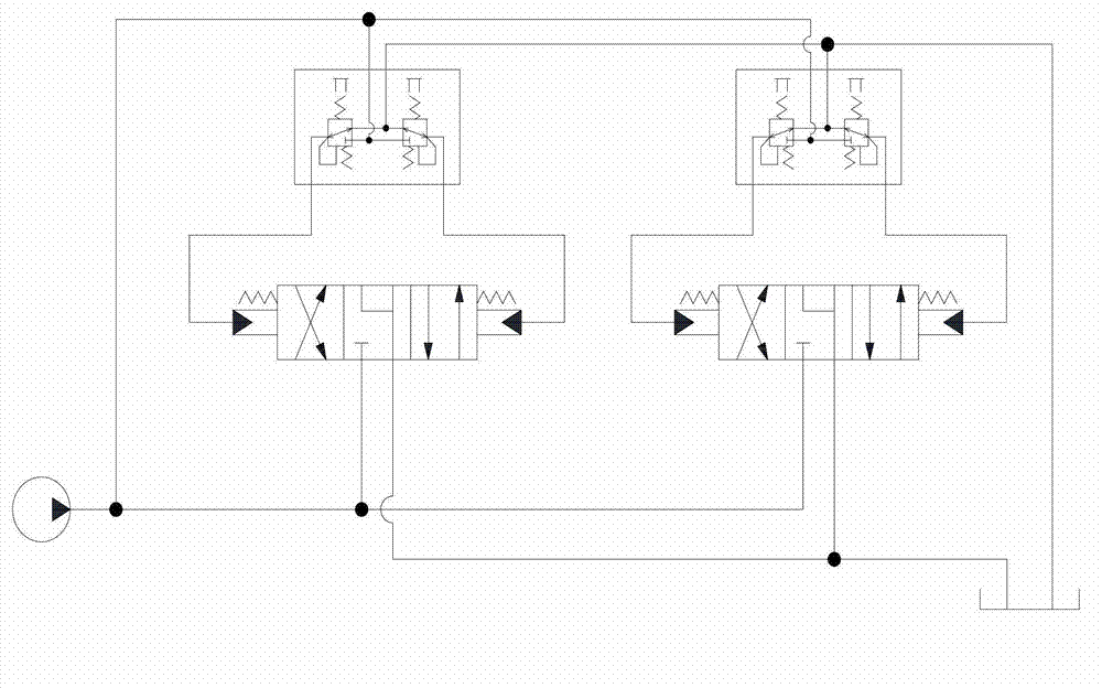
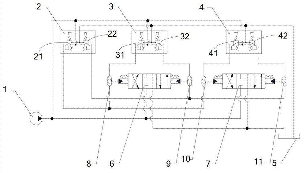
[0040] Below, combine figure 2 , the preferred embodiment of the hydraulic excavator travel control circuit of the present invention will be described in detail. The figure shows that the hydraulic oil passes through the variable pump 1, three pilot valves, two travel control valves and the oil tank 5 control circuit.

[0041] This embodiment provides a walking control circuit for a hydraulic excavator, including a first control oil circuit and a second control oil circuit; wherein, the first control oil circuit includes a connected first pilot valve (left pilot valve) 3 and the first travel control valve (left travel control valve) 6; the second control oil circuit includes the connected seco...


PUM


Abstract

The invention discloses a running control loop and a hydraulic excavator. The running control loop comprises a first control oil way, a second control oil way and a third control oil way, wherein the first control oil way comprises a first pilot valve and a first running control valve which are connected with each other; the second control oil way comprises a second pilot valve and a second running control valve which are connected with each other; the third control oil way comprises a third pilot valve; and the third pilot valve is respectively connected with the first running control valve and the second running control valve. By the running control loop, a problem that the hydraulic excavator easily deflects when moving forwards or backwards is avoided, the operation efficiency is improved, and the labor intensity is reduced.

Description

technical field [0001] The invention relates to the field of engineering machinery, in particular to a walking control circuit and a hydraulic excavator. Background technique [0002] The walking operation of the hydraulic excavator is carried out by switching the directional control valve for the left and right travel motors. This directional control valve is operated by two pilot valves. The existing hydraulic excavator travel control circuit such as figure 1 shown. [0003] For example: if the pilot valve is operated to the front at the same time, the directional control valves for the left and right motors will switch to the spool position in the forward direction, and the hydraulic oil will be supplied to the forward direction of the left and right motors, so that the motor can move forward. up. Similarly, if the pilot valve is operated to the rear at the same time, the directional control valves for the left and right motors are switched to the spool positions in th...

Claims


Application Information

Patent Timeline
Patent Type & Authority Applications(China)
IPC IPC(8): E02F9/22
Inventor 刘勇川本正治连加华
Owner SANY HEAVY MACHINERY
Why Eureka
Try Eureka