Hydraulic power-assistant valve device

A technology of hydraulic booster and valve device, which is applied in the direction of valve device, valve operation/release device, valve lift, etc. It can solve the problems of fast wear of the switch, large closing force, inconvenient use, etc.

Inactive Publication Date: 2013-01-23
SUZHOU YUDONG HVAC TECH CO LTD
View PDF6 Cites 9 Cited by
  • Summary
  • Abstract
  • Description
  • Claims
  • Application Information

AI Technical Summary

Problems solved by technology

Traditional valves are adjusted manually. In the process of adjusting the switch, manpower is required to overcome the pressure of the fluid. For large valves, it is often necessary to use a wrench, tools to open or manually open. Many valves exceeding DN100 are equipped with deceleration equipment. High cost, large volume, large closing force, difficult to close the valve, high labor intensity, fast wear and tear of each switch, and inconvenient use

Method used


Image

  • Hydraulic power-assistant valve device
  • Hydraulic power-assistant valve device
  • Hydraulic power-assistant valve device

Examples


Embodiment Construction

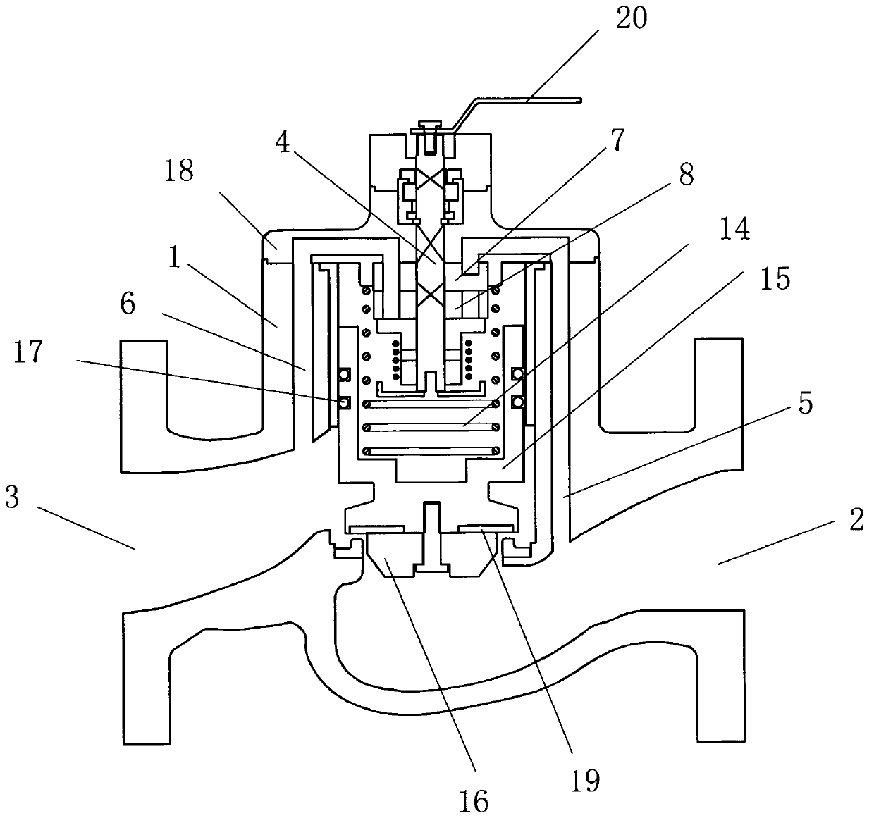
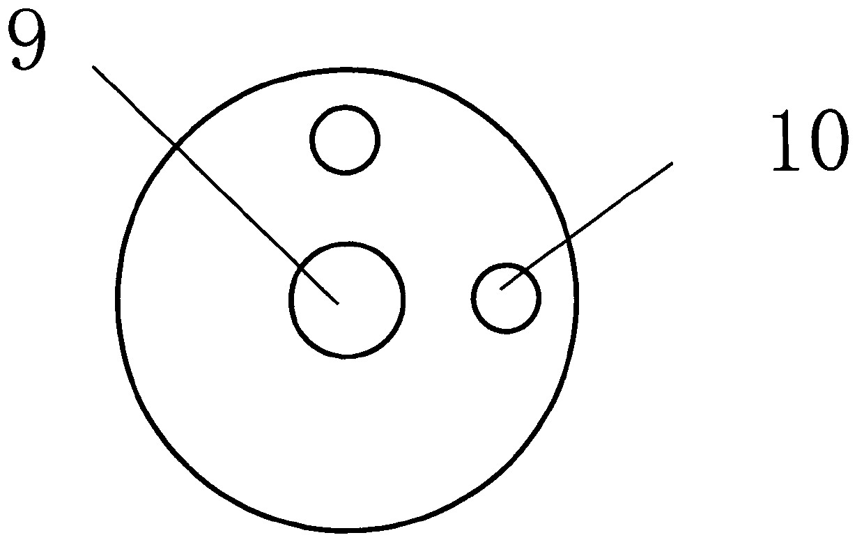
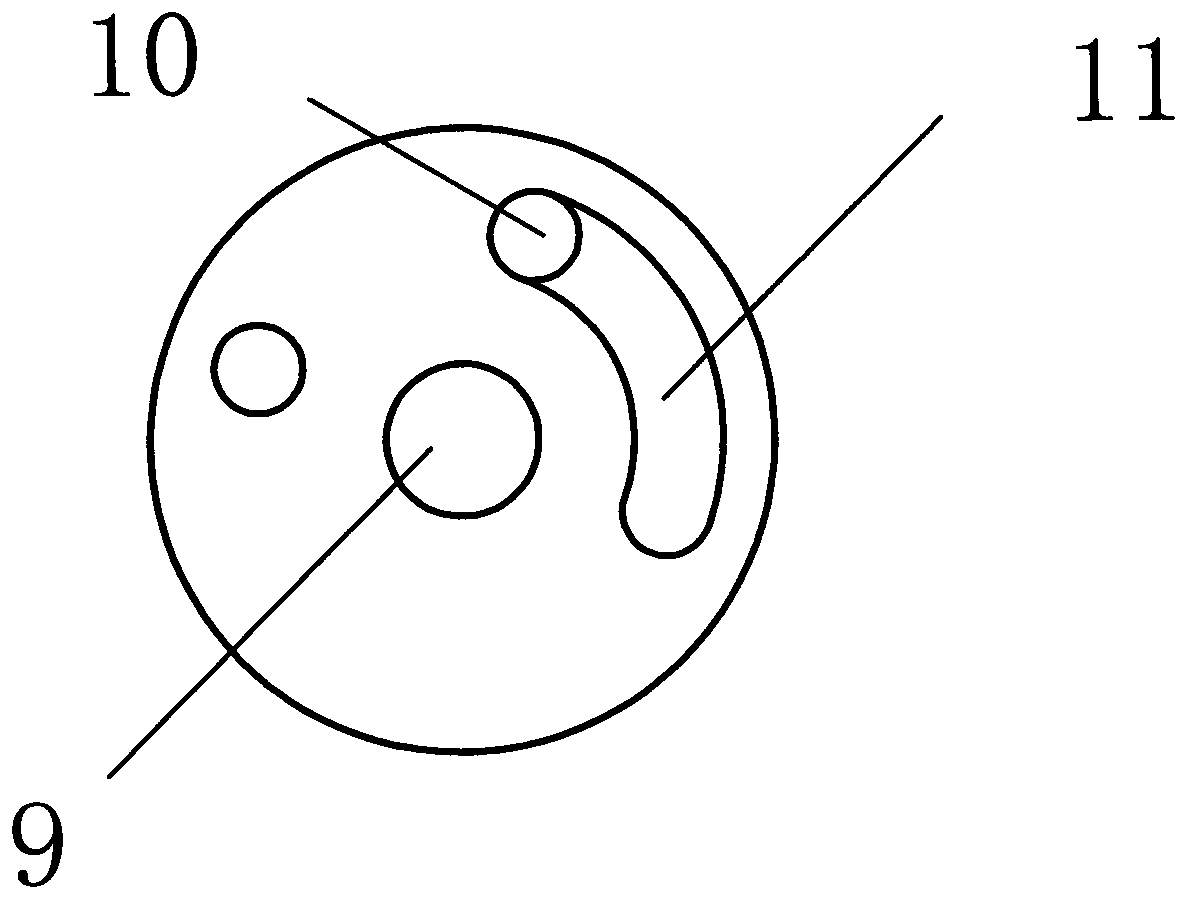
[0030] like Figure 1~5 The hydraulic booster valve device shown includes a valve body 1 with a cavity, which is different in that: the valve body 1 used in the present invention is respectively provided with a connected water inlet channel 2 and a water outlet channel 3, A valve core is arranged between the water inlet channel 2 and the water outlet channel 3 , a valve stem 4 is arranged on the valve core, and a conduction control assembly is arranged on the valve stem 4 . Specifically, the valve body 1 is respectively provided with a first channel 5 communicating with the water inlet channel 2 and a second channel 6 communicating with the water outlet channel 3 . At the same time, a valve cavity is formed between the cavity of the valve body 1 and the upper end surface of the valve core. In order to implement appropriate strength to shut off, an elastic component is arranged in the cavity, one end of the elastic component contacts the inner wall of the upper end bonnet of t...


PUM


Abstract

The invention relates to a hydraulic power-assistant valve device, which comprises a valve body with a cavity, and is characterized in that a water inlet channel and a water outlet channel which are communicated with each other are respectively formed in the valve body; a valve core is arranged between the water inlet channel and the water outlet channel; a valve rod is arranged on the valve core; a connection control component is arranged on the valve rod; furthermore, a first channel communicated with the water inlet channel and a second channel communicated with the water outlet channel are respectively formed in the valve body; a valve cavity is formed between the cavity of the valve body and the upper end face of the valve core; an elastic component is arranged in the cavity; one end of the elastic component is in contact with the inner wall of the valve body; and the other end of the elastic component is in contact with the upper end face of the valve core. Therefore, due to the matching of the connection control component, the water inlet channel, the water outlet channel and the valve core, under the action of the water flow to the valve core, the valve core can work, and pressure of fluid is not required to be counteracted by manpower; and a working state of the valve rod can be converted only with extremely small force, and the valve can be opened and closed.

Description

technical field [0001] The invention relates to a control valve, in particular to a hydraulic booster valve device. Background technique [0002] Valves are widely used in daily life and industrial production, mainly composed of valve body, valve stem, valve core and so on. Traditional valves are adjusted manually. In the process of adjusting the switch, manpower is required to overcome the pressure of the fluid. For large valves, it is often necessary to use a wrench, tools to open or manually open. Many valves exceeding DN100 are equipped with deceleration equipment. The cost is high, the volume is large, the closing force is large, the valve is difficult to close, the labor intensity is high, the switch wears quickly every time, and it is inconvenient to use. Contents of the invention [0003] The object of the present invention is to provide a hydraulic booster valve device in order to solve the above-mentioned problems in the prior art. [0004] The purpose of the p...

Claims


Application Information

Patent Timeline
Patent Type & Authority Applications(China)
IPC IPC(8): F16K1/00F16K1/36F16K1/46F16K11/074F16K31/12
Inventor 金哲龙
Owner SUZHOU YUDONG HVAC TECH CO LTD
Why Eureka
Try Eureka