Method for determining the tilt of an image sensor

An image sensor, pattern technology

Active Publication Date: 2013-01-23
AXIS
View PDF4 Cites 19 Cited by
  • Summary
  • Abstract
  • Description
  • Claims
  • Application Information

AI Technical Summary

Problems solved by technology

One problem with this method is identifying reflections from the image sensor, since multiple reflections are generated when the ...

Method used


Image

  • Method for determining the tilt of an image sensor
  • Method for determining the tilt of an image sensor
  • Method for determining the tilt of an image sensor

Examples


Embodiment Construction

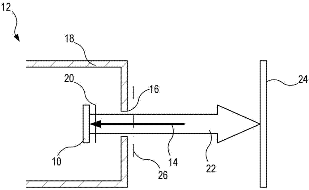
[0036] The present invention relates to the inspection of cameras, and in particular to the process of checking the tilt of an image sensor in a camera. now refer to figure 1 According to one embodiment of the present invention, checking the tilt of the image sensor 10 in the camera 12 includes sending light 14 onto the image sensor 10 through the image capture opening 16 in the camera body 18 . Depending on the design of the camera, light 14 may propagate through one or more transparent plates or transparencies 20 . The light 14 sent into the image capture opening is then reflected by the image sensor 10 and the transparent plate 20 , the reflected light 22 being illustrated in the figure by arrows returning from the image sensor 10 and the transparent plate 20 . This reflection is then captured on the analysis surface 24 where the resulting reflection pattern can be analyzed.

[0037] The light 14 sent into the camera 12 and onto the image sensor 10 can be transmitted to t...


PUM


Abstract

The invention relates to a method for determining the tilt of an image sensor. Specifically, the present invention relates to a method for determining a tilt of an image sensor surface plane in a camera in relation to a lens reference plane of the camera. The method comprises sending light onto the image sensor, receiving light reflected from the image sensor, identifying an interference pattern in the reflected light, identifying a feature of said interference pattern, and determining the tilt of the image sensor surface plane based on a position of the feature identified in said interference pattern.

Description

technical field [0001] The invention relates to a method for determining the tilt of an image sensor in a video camera. Background technique [0002] The quality of images obtained by cameras, especially surveillance and surveillance cameras, has improved, but the demand for higher quality images has also increased. One of the results of these requirements is the realization of image sensors with increased pixel count and reduced pixel pitch in cameras. However, in order to achieve higher quality images, other features should be considered besides the number of pixels and pixel pitch. [0003] For example, the increasing number of pixels and shrinking pixel pitch in image sensors has made image capture devices increasingly sensitive to misalignment between the image sensor and the optics that provide the image sensor with light representing a scene. Therefore, if the mounting accuracy of the image sensor is not high enough, the quality resulting from the increased number o...

Claims


Application Information

Patent Timeline
IPC IPC(8): G01C9/00
CPCG01B11/272H04N17/002G01M11/0257G01M11/0221H04N5/2253H04N23/57H04N23/55H04N23/6815H04N23/68
Inventor 约纳斯·耶尔姆斯特伦安德斯·约翰内松
Owner AXIS
Why Eureka
Try Eureka